The drawing of the MC
Solar needs some further description.
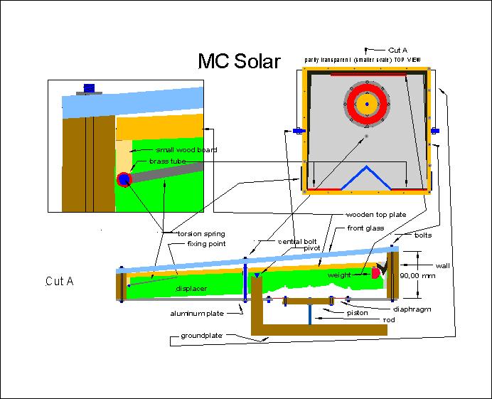
It shows in three views a 500*500mm size horizontal version of a motor for
a solar powered water pump. The drawing has (almost) no sizes mentioned in
it, because the engine can be build in different forms (rectangle, square,
even circular shape) and sizes up to about one square meter. So, all the
below mentioned numbers and measurement are only for a 500*500mm application
and have to be modified for other sizes and/or forms.
The stroke of the displacer(for a 500*500mm engine) is best at about
40mm (measured at its right end), supposing 60 upward- and downward movements
a minute. The bigger the engine, the slower it will move, so when you build
a one-square-meter engine 60-80mm will be better. If you mount magnets to
the engine (see below) this will speed up the engine. But you cannot enlarge
the stroke very much, thinking you will get a greater amount of expanding
working volume ! Why ?-> The amount of energy per square meter coming
from the sun stays the same and during one second this amount of energy CAN
ONLY HEAT UP SOME LITERS OF AIR to the temperature needed in a machine like
that. So more air (to heat up) at the same frequency, has the effect of a
lower temperature at the hot side.
Depending on size and form, the amount and position of the central bolt(s)
has to be modified. At the bottom of the page you see a cut through the
engine.
To the left there is a detailed (enlarged) view of the axis (torsion
spring) and to the right a partly transparent (smaller scale) TOP VIEW.
The hole engine(cylinder) has to be build airtight, which can be best achieved by using silicon paste (purchasable in any hardware store for sealing bathroom ceramics).
During the first few weeks of that website I showed an engine with a tube-regenerator here. For the sake of more simplicity and the fact that the tube is hard to fix at an old car-windows-glas I have a better design now.
So, let's start the description at the left side of the Cut A. The
bottom of the MC Solars
cylinder is made of a 3mm aluminum plate.
A steel sheet (2mm) will work too. A bigger engine needs a thicker metal
or the bottom plate has to be sickle-shape(bow-shape),
so it can resist the pressure differences.
.The top of the engine(cylinder), the front glass, is of 8mm transparent
(carbonic) plastic. In Germany you can purchase this plastic as 'Macrolon',
but other materials might do as well, as long as it stands the heat of about
100 degrees Celsius and of course the pressure differences. Quite well applicable
are old car windows. Even usual glass can be used.
What is NOT in the drawing is another sheet of transparent material above
the front glass (as a kind of cover against the cold ambient
air(double glass)), which needs NOT to be very strong. Usual 1mm plastic
foil (for gardening), mounted in a few millimetres distance from
the front glass and sealed at its sides, helps a lot.
The walls of the engine(cylinder) are made of wood and 20mm thick.
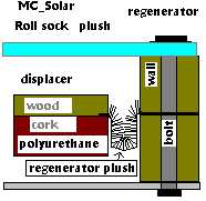
The bottom part of the displacer (green) is made of polyurethane foam.
These plates you can purchase in a hardware store for roof
insulation.
Polystyrene foam is NOT good here, because of its low melting point.Other
materials for the displacer are cork (or processed cork or backed
cork),
balsa wood or any other, quite light, wood. The polyurethane part of the
displacer is hollow near the piston for the piston to fit
in,
at the point of highest compression.
The top of the displacer is made of 10mm plywood and it has to be
blackened (Caution: Use color, that can stand at least 100 degrees Celsius!)
to absorb the heat from the sunrays. As well, or even better is a black terry
cloth on this surface and even black velvet is a good choice.
So the hole displacer is about 50mm thick (or thicker, depending on
the material available for you).
The JPEG DOESN'T SHOW WELL the plush regenerator and form of the displacer
(TOP VIEW black wedge-shaped at the sides).
This easy type of regenerator in fact is a layer of usual plush, like
plush for teddy bears(about 10mm thick).
See the little detailled view. It
is formed
like a sealing, in slope form, so it lets the displacer move freely.
You might mount a double layer as well, depending on the
weight
of the displacer and the density of the plush. Instead of plush
some artificial furs can be used too. The advantage of this
plush
regenerator in relation to the tube regenerator is, that it is easier to
build. The gap covered by the plush is 20mm at its widest.
Try a smaller gap, if you have thinner plush and vice versa.
The central bolt passes through the displacer and keeps the front glass and the aluminum plate from bending, because of pressure changes.
The weight (about 500-1000 grams iron) here is to give enough kinetic
inertia to push the air from the hot to the cold side and vice versa.
It has to be balanced to the tension of the torsion spring (about
5mm steel depending on the angle to the sun and the weight in the
displacer) to about equilibrium. By the form of that torsion spring
(blue), you can see (in the TOP VIEW), that it has to be fixed to the
plywood plate at the uppermost point(TOP VIEW). In the detailed view on the
left, you see a small wood board between the plywood plate and
the torsion spring (axis). It's there to stabilise and hold the brass
tube.
The brass tube is 150mm long and acts as a bearing here to the steel
(torsion spring). Outside the engine(cylinder) the torsion spring
has to be
FIXED (after balancing it to the weight).
The pivot is just a wedge shape screw in the hollow shape stand. As
well you might use a usual ball bearing here, if you like. The best position
for the pivot is naturally about in the middle, at the engines equilibrium
point (except for self starting).
The piston is a 100mm diameter wooden disc (or even better an aluminum disc), that is fixed with a long screw as a rod to the ground plate.
The diaphragm is made of rubber foils (1-2mm).
The bolts I have used were 4mm, with washers(20mm).
To extract power from the MC Solar you have to mount a pushing rod to the wall of the engine(cylinder). Best and easiest will be a diaphragm pump.
To enhance the power output (and the frequency) or to control the stroke
length, you might mount stops (by using usual springs) to the cylinder,
but no exact experiments about the force and size have been done by me yet.
As well you can connect a rod to the cylinder and drive a flywheel
with the MC Solar.
The drawing shows an engine in a horizontal application, but the MC Solar
can be adjusted to ANY ANGLE (even vertical (see
MC_easy)),
as long as the force of the torsion spring is in balance with the
weight.
Instead of the torsion spring mechanism, you might as well build a
usual axis and fix a usual spring under the displacer. The only problem
is
to find a spring, that keeps its force constant throughout most of the stroke
length of 40mm (which might be a problem!?).
The engine(cylinder) in that configuration will not self start. After one
or two minutes of heating up in the sunlight, you have to tip it and it
will start. If you want to make it self start, you need to have the
pivot more to the (see drawing) left, that way, that the right side
(cold engine)
sinks down and you need to fix a permanent magnet to the ground plate
that way (underneath a screw of the aluminum plate), that it holds
down
the cylinder a bit. So, when the engine is (gets) cold the right side (see
drawing) will sink down and will 'anchor' to the magnets force. If then
the sunlight heats up (again) the air, pressure raises up to the point, where
the magnets force can no longer hold the cylinder. So the cylinder
will move up, the displacer with its inertia will even push more air
to the top and enhance pressure and the first stroke is started. On the way
up,
when the pressure has done its work and the cylinder tends to stop, the
displacer(still having speed) moves further upward and pushes the
hot air through the regenerator down to the aluminum plate
chamber. Underpressure raises and the engine(cylinder) is sucked back
again....and the engine
is running.
Self staring is not that easy to achieve and needs some good balancing...and
it's hard to build it 100% self starting, because absolute airtightness
is necessary.
After assembling the engine it is important to check:
- if the displacer is moving quite freely (with little friction)
- the cylinder is really airtight.
You can achieve about 30 Watts per Square meter with a MC Solar. Depending
on the size about 60 cycles per minute will be reached.
Power output can optimized by:
- finding the best fitting piston diameter for the average sun radiation
you have and by that finding the best relation of your displacer
stroke
(40mm) to your cylinder stroke.
- building a water jacket to the aluminum plate
- building a inner water jacket on the surface of the displacer, having
the axis (torsion spring) as a tube for water in- and outlet
- using special glass with a oneway behaviour for heat radiation
- with the help of magnets on the aluminum plate and the front
glass acting on the displacer, the optimal movement of the
displacer can be
Ā achieved (which is displacing the air in the very last phase of the
stroke).
- mounting springs that act like stops to find the best stroke length and
frequency for your engine
This description is a very short one and it will be improved soon.
Download:
Drawing as JPEG Ā Ā
This page will be updated to further research data to it and help you find the best materials and configuration for your needs.
For further information write to: Ā Ā Āhustierhof@aol.com