
|
|
|
| Introduction The cross field antenna,or CFA seems little understood amongst the amateur population and is an antenna which is not widely written about, except for a few places on the Internet. It is an antenna which some have spent considerable energy in the persuit of showing that it is no different from antennas which have come before us. The purpose of this article is to relate my experiences with this antenna showing that this antenna with a height of 1.5% of a wavelength is indeed a stiff competitor to a quarterwave vertical. For background material on this antenna I recommend you do a search on the internet under "crossed field antennas" , there is a paper still readily available called "NAB99 CFA" which gives some good background info, and if you are serious about CFAs then WWW.antennex.com is the place to visit. Theory of Operation My explanation here is basic but the concept is one that needs to be grasped. As we all know radio waves consist of an electric and a magnetic field displaced by 90 degrees. This antenna operates by separately creating an electric and magnetic field with the required displacement of 90 degrees to synthesise electromagnetic radiation. The magnetic field is produced by the "D" plate or disk |
acting as a capacitor against the groundplane, the current that flows
through this capacitor produces a magnetic field. An electric field is
produced by the "E" plate or cylinder by virtue of the voltage applied
between it and the ground plane. Power from a transmitter is split in two
and displaced by 90 degrees by a tuning and phasing unit and applied to
the two elements of this antenna. In an area known as the "IZ" or
Interaction Zone where the electric and magnetic fields cross, radiation
"S" is produced. For radiation to take place two conditions need to exist:
1. Angular displacement of 90 degrees between the electric and magnetic
fields. 2. Equal amounts of power in both electric and magnetic fields.
|
Antenna Dimensions After spending considerable time experimenting with different sized ground planes and conical extensions to the "E" Plate to realise a comparable radiated field strength compared to my quarter wave vertical, I have come up with the following dimensions. These dimensions are not the "be all and end all" as far as CFA development is concerned, however if you follow these dimensions you will have a unit that works well for 20 metres at least.Now it's time to build! The Ground Plane I originally tried with just a 60 cm diameter ground plane, but later discovered that 1.25m diameter ground plane gives a performance almost like a vertical, also making it more docile to tune up. If you use flat galvanised steel as I did then some mechanical support is needed. Cylinder and "D" Plate The cylinder was taken from the kitchen pantry, a tin measuring 10cm diameter and a height of 12 cm. The top and bottom removed with a can opener leaving the rims intact. The "D" Plate is cut from 0.4mm flat galvanised steel, Diameter is 20 cm. Centre hole is 4cm cut out with a nibbling tool. Galvanised steel was chosen because this material is readily solderable an still not too expensive from the hardware store. The tin will need to be painted, as it will rust in the fullness of time when exposed to the weather. The Cone Sections of the E Plate The material used is 0.4mm flat galvanised steel. The first section on the cylinder gives an additional 5cm height with the diameter increased from 10cm cylinder to 20cm a fairly steep section.The second section is much more shallow and was created by drawing 2 concentric circles 14 and 20 cm diameters and cutting the center out, the resultant ring is cut in one place and pulled up to give a cone height of 3cm. this is mounted on the previous section. Leave some tabs on the cut out to allow attachment of each section. |
  Ground Plane underside 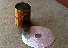 E1 and D Plate  A conical Section cutout |
| Spacers The spacers which support the "D" Plate off the ground plane and the "E" Plate are cut from 2 cm PVC electrical conduit to give 5 cm spacing between each antenna element. The spacers which support the "E" plate have a notch cut in them to receive the rim of the cylinder. Assembly I used some long cable ties to hold it all together. On the bottom of the cylinder 3 holes were made at 120 degrees apart to anchor the cable ties to the bottom of the rim. Note that the electrical connection to the "E" Plate has already been prepared at this stage. This manner of connection is used to equalise the current distribution around the cylinder. 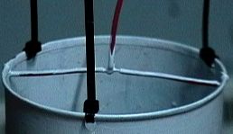 (Assembly stage 1.) 3 of the spacers are then slid over the cable ties.  (Assembly stage 2.) |
The cable ties are then passed through matching holes in the
"D" plate. The buckle of another cable tie is used to lock up the "D"
Plate, spacers and "E" Plate together. Note the similar method used for
the electrical connection to the "D" Plate.  (Assembly stage 3.) The same process is repeated again locking the whole assembly against the ground plane.  (Assembly stage 4.) The Tuner - introduction Since the inventors of the Crossed Field Antenna had filed patents on their antenna design, information on the circuitry used in their commercial broadcast antennas has been kept under wraps; leaving the amateur to find out for himself the hard way through much experimentation. The circuit used here is probably the simplest, it does work, but it does have limitations when it comes to multiband operation. The capacitive reactance presented by the "E" and "D" plates will vary significantly from band to band, necesitating readjustment of transformer windings and values of capacitances used in the circuit. The profile of the "E" Plate and the size of the ground plane will have a profound effect on the radiation efficiency. |
| Many experimenters appear to have given up
early having the impression that the CFA antenna was not much better than
a dummy load or wet piece of string. Tuner - the details The tuner is based on a transformer wound on a 50mm iron-powder toroid which is t-200-2 Toroidal core, wound with 1.6mm dia wire. The secondary windings L1b and L1c are bifilar wound. The primary L1a is simply wound between the bifilar turns as shown in the picture. (coil side). The capacitors used can also be the air spaced ganged tuning capacitors once found in domestic valve receivers. The purpose of capacitor C1 , is to tune out the inductive reactance of the primary winding L1a, it becomes series resonant. Once this capacitor is set correctly you will find that no further adjustment is required for the whole 20 meter band. The magnetic field produced by the "D" Plate leads the electric field produced by the "E" plate by virtue of the fact that current into a capacitor leads the voltage. It is this current that produces the magnetic field. The purpose of C2 is to cause the electric field produced by the "E" Plate to lag the magnetic field by 90 degrees. Its function is purely that of phase angle adjustment, (and not making the E Plate to be resonant). |
 The
CFA Tuner Circuit Diagram The
CFA Tuner Circuit Diagram 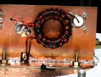 CFA Tuner (coil
side) CFA Tuner (coil
side)  CFA Tuner (capacitor side) |
|
Tuning Up (or trying to:-) |
From this plot you will soon realise the necessity of
remote controlled capacitor C2 in order to move up and down the band.
Performance You will find this antenna "hears" differently to a vertical, powerline noise is vastly reduced. You may well wonder if it really works. A little probing with a field strength meter and you will find the field squirts well out of the side and not much at all at higher angles, I finally ended up mounting it on a post 1 metre above the roof, this seemed to give a feel somewhat similar to a vertical but still different. Some test were performed comparing the CFA against a quarter wave vertical as a reference antenna; Ground wave signals: it was generally found that the CFA was equal to or slightly better. Mounting the CFA low on a large flat aluminium roof enhanced the signal by more than an S point in the favoured direction of the extended ground plane of the roof. With the antenna in it's present position (1 metre above the roof) the ground wave signal is almost gone. Short Skip <2000Km: Signals are well down at least 2 S points or more, this is consistant with what was found with the CFAs used for broadcast service, that is very little skywave radiation. Long Skip 4000Km: (max F2 distance) , The CFA's low angle of radiation enables it to compete quite well with the vertical and the narrow bandwith of the tuning/phasing network makes it a quieter antenna at the same time. Much work has yet to be done in order to find out just what the radiation pattern is like for a given antenna profile and different size ground planes. (Thanks to VK2OM, VK2JY, VK2TEK and VK2AWD for encouragements and numerous signal checks) Top of Article Home Page |

