

October 15th 2005
Early Beginnings
First Engine
Video
Contact Me
Readers Comments
Links
Project Quick Links:
· New Changes
· Testing


Until next time, Thanks for reading.
|
|||||||||||||||||||||||||||||||||||||||||||||||||||||||||
|
|||||||||||||||||||||||||||||||||||||||||||||||||||||||||
| Last Updated: October 15th 2005 |
|||||||||||||||||||||||||||||||||||||||||||||||||||||||||
| Garage Jet Early Beginnings |
|||||||||||||||||||||||||||||||||||||||||||||||||||||||||
| Main Page First Engine Video Contact Me Readers Comments Links |
|||||||||||||||||||||||||||||||||||||||||||||||||||||||||
| Starting out this project I knew I needed two major things, a turbocharger, and a combustion chamber so that was my main focus in he beginning. First I went looking for a turbocharger. Finding a turbocharger isn’t the easiest thing. I was at the junkyard a few times trying to take turbo’s off cars. Most turbo’s were damaged or the bolts were rusted on. I searched all over ebay and couldn’t find anything for a reasonable price until I found a Mitsubishi T2 turbocharger for $60. | |||||||||||||||||||||||||||||||||||||||||||||||||||||||||
| TT1 Project Quick Links: |
|||||||||||||||||||||||||||||||||||||||||||||||||||||||||
| · Early Beginnings · New Changes · Testing |
|||||||||||||||||||||||||||||||||||||||||||||||||||||||||
|
|||||||||||||||||||||||||||||||||||||||||||||||||||||||||
|
|
|||||||||||||||||||||||||||||||||||||||||||||||||||||||||
| Visitors Since 10/14/05 | |||||||||||||||||||||||||||||||||||||||||||||||||||||||||
| Unfortunately this turbo was dead on arrival. It had a bad crack in the exhaust housing where the waste gate used to be and leaked out really bad into the compressor and exhaust. It also had too much endplay and rubbed on the compressor housing. I bought it on ebay but the guy that sold it to me took so long to ship it that it was to late to file for ebay fraud protection. So I still need a turbo and I am out $60. I’ve been looking for parts to make a combustion chamber with but I’m not having much luck. I think I’ll try and use automotive exhaust parts. | |||||||||||||||||||||||||||||||||||||||||||||||||||||||||
|
|||||||||||||||||||||||||||||||||||||||||||||||||||||||||
|
|||||||||||||||||||||||||||||||||||||||||||||||||||||||||
| Above Here’s the finished combustion chamber. Before welding I was a little unsure and now I am certain. Its ugly, it’s not going to seal properly, it’s not designed very well, it looks unsafe, and welds are extremely crapy and its probably weak and might melt. So it’s out of here, scrap metal. I am really not starting out so good. I bought a ’98 mustang fuel pump and tested it a bit but now its fried and I need a new fuel pump too. In august 2003 I am starting classes at Piles Peak Community Collage. I am taking a 2-year course at collage during my high school time to earn high school and collage credits. I will also be staring 11th grade, august ’03. I've found an ignition circut I'm going to try and reproduce. |
|||||||||||||||||||||||||||||||||||||||||||||||||||||||||
|
|||||||||||||||||||||||||||||||||||||||||||||||||||||||||
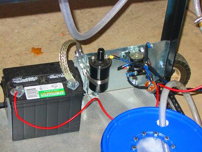
| Above heres my Ignition system I can't get to work. Bottom right you can see my fuel tank. I cut out a plactic window on the laser at the collage so I can see how much fuel is left. I used 10 bolts to seal it to the lid. the tank holds 2.5 gallons. I’ve started machining classes and it’s a lot of fun. There are many manual lathes, manula mills, CNC lathe, two CNC mills, a Laser and a few pro-light maching ceters at the collage. I am learning lots of new things. Hopefully at the end of the 2years I’ll be able to operate a CNC machine. I’ve been working on a few parts for my combustion chamber in machining class. I’ve made the fuel injector holder I’ll have to weld to the combustion chamber later. I’ve also ordered a few hago oil burner nozzles and a special tap so I can tread the nozzles into the injector holder I machined on the lathe. I have also worked on my oil system too. Below I’m using an electric wheel chair motor connect to a small block Chevy oil pump. I bought both on ebay. I’ve made piece on the lathe at the collage that joins the shaft of the motor to the shaft on the pump. They are very different in size and shape but it was an easy part I made quickly out of T6061 aluminum (aircraft grade). The electric motor powering the oil pump spins at 3,300 rpm. On a Small block Chevy motor the oil pump spins at half the engine’s speed. Red line on a small block Chevy I imagine is around 6,000-7,000rpm so the pump will be running at speeds it would only see at red line on its original application. This should provide good oil pressure but I am not sure how well it will do long term. | |||||||||||||||||||||||||||||||||||||||||||||||||||||||||
|
|||||||||||||||||||||||||||||||||||||||||||||||||||||||||
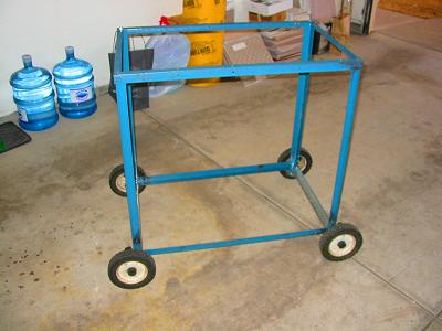
| The oil pumping system work but it also leaks. Leaks are ok as long as they aren’t too bad. If it leaks it just drips down into the oil reservoir. I’ve been working on making a test frame for my engine. I’ve been making it out of an old bed frame. I’m still looking for a new turbo and I still need a combustion chamber. | |||||||||||||||||||||||||||||||||||||||||||||||||||||||||
|
|||||||||||||||||||||||||||||||||||||||||||||||||||||||||
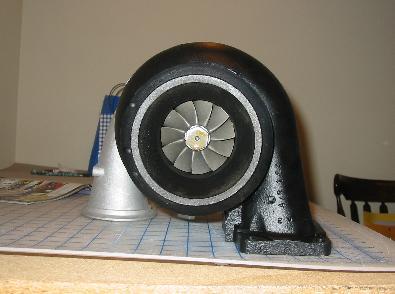
| I’ve found a turbocharger! I went to interstate turbo in Denver Colorado. Diesel truck turbocharger off a Detroit diesel series 60 engine. It’s a pretty big turbo compared to the old one. It’s got a 2.5inch inducer diameter. It also bran new! Never been used. It spins very freely and has absolutely no shaft play at all. The shaft is solid. Doesn’t move the slightest bit in any direction. I just need to find a compressor map for this turbo. | |||||||||||||||||||||||||||||||||||||||||||||||||||||||||
|
|||||||||||||||||||||||||||||||||||||||||||||||||||||||||
|
|||||||||||||||||||||||||||||||||||||||||||||||||||||||||
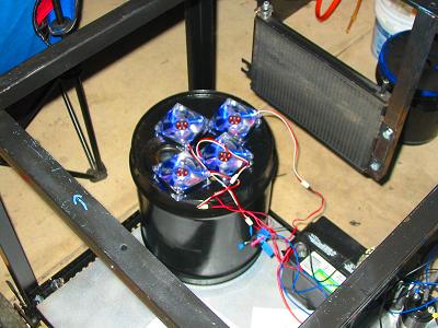
| I bought my second fuel pump. It’s a Toyota corolla fuel pump. It’s only capable of 55psi so I’ll needing a second one of a completely different on capable of at least 100psi on it own. Below you can see some testing I’ve done with my new fuel pump and oil burner nozzles. I am using .75 GPH oil burner nozzles at 50psi. You can feel the intrense heat from a few feet back. | |||||||||||||||||||||||||||||||||||||||||||||||||||||||||
|
|||||||||||||||||||||||||||||||||||||||||||||||||||||||||
| I’ve made a control panel and have it mounted to the testing frame. I still need to get working on my combustion chamber. I still also need an ignition system and better fuel pump. I’ve bought 4 computer-cooling fans to mount to an oil cooler to cool the oil. than fans arn't mounted yet. Below is a picture of current progress. | |||||||||||||||||||||||||||||||||||||||||||||||||||||||||
|
|||||||||||||||||||||||||||||||||||||||||||||||||||||||||
|
|||||||||||||||||||||||||||||||||||||||||||||||||||||||||
| Below is what I’ll use to read oil and engine temperature, it’s a K type thermocouple. I bought this off ebay as well. It is going to Velcro to the control panel. | |||||||||||||||||||||||||||||||||||||||||||||||||||||||||
|
|||||||||||||||||||||||||||||||||||||||||||||||||||||||||
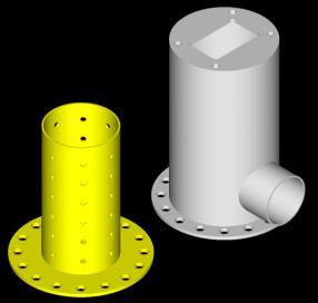
| I’ve finally been learning some stuff on the CNC mills. I plan to make some complete combustion chamber on the CNC machine. I’m going to go to western steel scrap yard to buy some scrap metal to machine into a combustion chamber. Below I’ve made a rough draft on auto cad of what my engine is going to look like. I’ve taken 3 years of auto cad (computer aided drafting software) in school and I also have it on my home computer. I’m also currently learning master cam (computer aided machining software). The two are compatible to an extent. I find auto cad to be a lot more user friendly but master cam is defiantly where it’s at. You can draw just about the same but then you can tool path and generate “G” code as well. G code is what runs the CNC machines. Similar to coordinates on a grid but a lot more complex. | |||||||||||||||||||||||||||||||||||||||||||||||||||||||||
|
|||||||||||||||||||||||||||||||||||||||||||||||||||||||||
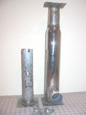
| Today I finished the combustion chamber. It was made of .25inch thick mild steel. It has 20 bolts holding the flame tube to the air casing just like the design above. I bough the two tubes used for the air casing and the flame tube as western steel scrap yard in Colorado springs. There are 5 plates I had to machine for this combustion chamber. 4 of them I produced on the CNC mill. There is the one plate that welds to the top of the combustion chamber so it can bolt to the turbo. Another plate welded to the bottom of the air casing with holes drilled in it so it can bolt to the 3rd plate that is welded to the bottom of the flame tube. There is a fourth plate I made that welds to the air delivery tube and clamps to the turbo’s compressor discharge. The fifth plate is the one on the other side of the air delivery tube. It had to be bent to fit the contour of the air casing. The tube I will be using to attach the compressor discharger off the turbo to the combustion chamber was bought on ebay for another project. It is a racing cold air induction for a 1992 Honda Prelude. I am also into fixing up cars and I bought this for separate project I am currently working on. But I’ve got a few so I decided to take this one and chop it all up into little pieces… then weld it back together so it’s the right shape and has the right curves. I want to try and create a swirl in my combustion chamber so the air mixes better with the fuel. I’ve tried to offset the incoming air tube to one side to do this. I haven’t tested this yet but it looks nice :) Until next time, Thanks for reading. |
|||||||||||||||||||||||||||||||||||||||||||||||||||||||||