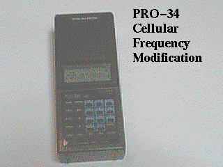
The following document explains how to modify a Radio Shack Realistic Pro-34 scanner to receive the 800 mhz cellular telephone frequencies which were disabled prior to the unit being sold.
This modification is specifically for the Pro-34. There are other mods available for other scanners, but this document does not cover those.
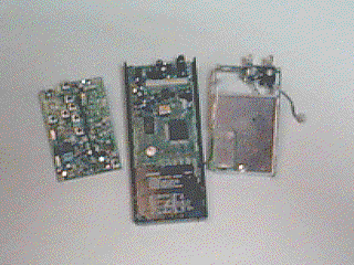
This mod is more difficult than those for many other scanners. It involves the delicate use of a soldering iron, and the removal of many parts of the scanner chasis in order to access the single diode you need to clip. If you are not sure of your skill in accomplishing this mod, at any time during your attempt, do not advance any further, as a slight mistake can render your scanner inoperable.
Tools required:
There is currently legislation in Congress which, if passed, would make it specifically illegal to modify a scanner. It is unknown whether the intention of those capable of enforcing such a law, would be to try to enforcing it retroactivly.
You assume all risk, legal and technical, if you decide to undertake this modification. While it might be illegal to modify a scanner to receive cellular communications, certainly it can't be illegal to have, obtain or distribute the information detailing how such a modification can be done.
1. Remove the volume and squelch knobs from the scanner by pulling them off.
2. Remove the battery compartment cover and battery pack.
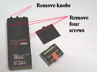
3. Remove the four screws on the back. (Not the beltback screws)
4. Remove the back cover. Lift the lower end up and then slide the entire cover off, over the volume and squelch control shafts.
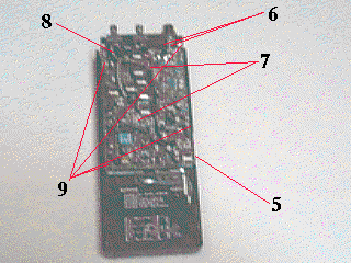
5. Unsolder the ground strap on the lower right side of the upper circuit board.
6. Unsolder and remove the antenna connector. First unsolder the ground strap and bend it back to allow the loosening of the BNC connector retaining nut. Loosen the nut and unsolder the BNC center lug, removing the antenna connector.
7. Unplug the volume and squelch harnesses from the circuitboard.
8. Unsolder the ON/OFF switch leads from the circuit board.
9. Remove the four post studs.
10. Gently pull up, and remove the upper circuit board.
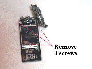
11. Remove the three screws holding down the RF shield cover and chasis frame.
12. Remove the chasis frame, carefully unplugging the connector from the lower circuit board.
13. Clip diode D-11 on the lower circuit board.
14. Reasemble the scanner in the reverse order.
Should you have the desire to download this entire page, pictures and all... s'pose you are concerned that the US Government might desire to censor the content of this page, then you can download the packaged file right HERE
