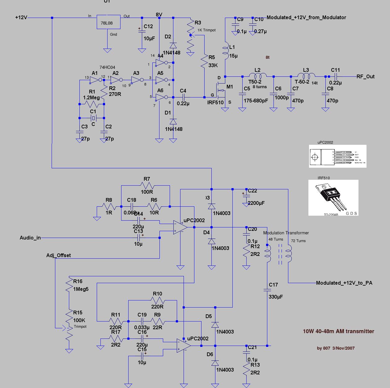
40-48m 10Watt AM Transmitter
This design is presented for educational purposes only. It does not purport to represent state of the art or an "easy to build" project. A low power transmitter like this is not difficult to build for someone who has a bit of RF experience. However, like anything else it takes time to get experience. I've been forcing electrons down wires for 40 years and despite a thick skull, I have picked up some skills over the years. For someone who has never built any electronics, let alone RF, this may be an impossible project.
The circuit
Nothing in this transmitter design is new or novel, and in fact most of the design has been ripped off from other places. None of the circuit could be called optimised, I built this one unit and it works. I haven't made any attempt to use easily available parts, what I used was what was in the junk-box and what worked. It was all built dead bug style and some bits of copper PC board. PCBs are nice, but for a one off it takes more time to make the PC board than build the rest of the transmitter. Also a plain copper ground plane makes life a LOT easier at RF.
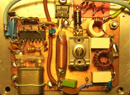
This is a view of the RF part of the Transmitter. Note that slightly different toroids were in use at this stage and each have an extra turn on them. The zig-zag of diodes at top right is a peak voltage protection string I'm working on to try to make the PA 'pop' proof.
Xtal Oscillator and RF driver
I used one section of a 74HC04 hex inverter as an xtal oscillator, the circuit is the standard Pierce logic oscillator circuit. If you want to trim the frequency of the xtal a bit try varying the value of C3. Varying C2 will have some effect, but not as much.
The signal is buffered, or squared up by 2 more inverters and then drives 3 inverters in parallel. The 3 inverters in parallel provide just enough drive for the IRF510.
Note that the 74HC04 is specified to run on 5 Volts. To get enough oomph to drive the MOSFET, I am running it at 8V from a 74L08 regulator. This is pushing the specs quite a bit but has been reliable in other transmitters. Note that exceeding 8V by any significant amount may cause disaster - ie blown chips. Also I buy these chips in bulk and have always used ones from the same manufacturer (Fairchild?). Other manufacturers chips may not like 8V on them!
The 2 x 1n4148s between the supply rail s and the commoned output for the three inverters prevents any spikes back from the PA stage destroying the 74HC04. Since I stated using these diodes I have had very few 74HC04s fail. I'm not sure exactly what the failure mechanisim is, but the 74HC chips sure don't seem to like higher voltages.
PA Stage
The IRF510 PA stage if pretty standard. Its not class ‘E’ or anything high tech. Bias voltage is applied to the gate of the IRF510, so that we can get away with less drive from the CMOS driver stage. The turn on voltage of a MOSFET is abound 3Volts, which is where you would expect the bias to be optimum, but I found that it was best significantly higher at about 6V. I would expect that under these conditions if the xtal oscillator stops, the IRF510 will get REAL hot, and draw significant amounts of current. It would be better to derive the bias from the drive, so if drive fails, tha PA will just be switched off.
L1 is rated at three amps, you need something reasonably low resistance here, those little moulded chokes will probably pop pretty quickly if used here.
C5,C6 and L2 form a matching network to transform the RF impedance of the antenna from 50 ohms down to about 10 ohms . C5 is a compression trimmer, and thus can be adjusted. L2s inductance can be varied significantly by either evenly spreading the turns around the toroid or bunching them up. I tuned for lowest current to the PA for ~ 10 Watts output, not spectacularly scientific, but it works. The adjustment isn't too critical.
C7,C8 and L3 from a simple Pi network low pass filter. Capacitors C5,C7,C8 should be Silver-Mica or Polystyrene . In a pinch you could use NP0 ceramics. C4 & C11 were normal ceramics.
Modulator
The modulator uses two "Pentawatt" package audio amps in a bridge arrangement based on an app note from some data sheet I had laying around.
On testing I found that a single uPC2002 (TDA2002) running into a 2 ohm load could generate a maximum output of 8.3V peak to peak.. Using 2 x uPC2002 in bridge mode the effective peak to peak voltage is 16.6V into a 4 ohm load. To fully modulate a 12V PA we need a peak to peak voltage swing of 24v. ( That is a positive swing of +12 that adds to the standing voltage of +12 to produce a peak voltage on the PA of 24V and a swing of -12V that will subtract from the standing 12V to produce 0V on modulation troughs. It would be nice to have the capacity for a higher pk-pk voltage swing , but we're operating quite close to the chips specs.)
To get the 24V swing I used a transformer with a 1:1.5 step up ratio. The PA stage presents about an 10 Ohm load to to the secondary of the transformer (13V/1.3A= 10 Ohms). The impedance ratio of a transformer is the square of its turns ratio. 1.5 x 1.5 = 2.25 so the load presented by the primary to the modulator is 10/2.25 = 4.4 ohms which works out as 2.2 ohms per uPC2002 chip wich neatly lines up with the 2 ohms I initially used for testing.
The series parallel R/C networks C19/R9 C18/R6 provide a high frequency roll off at about 10Khz. I'm not really sure if this is required for stability. Its only 4 extra components so I left it in. The zobel networks C20/R12 C21/R13 are NOT optional. Leave them out and the '2002s will oscillate - not a nice audio oscillation, but a supersonic, full bore "chip gets really hot and draws LOTS of current" oscillation. Without a CRO, the only way you will be aware of this oscillation is that they will get real hot and produce nasty distorted audio. Make sure these networks are close to the output pin of the audio chips and the components have short leads!
The 4 diodes D3-D6 protect the uPC2002s from any back EMF from the transformer that may arise due to operating with no load on the secondary of the transformer or switch on transients. Transformers can generate very high voltage nasy transients if there is any sudden change in current through them. The diodes are cheap insurance.
Modulation Transformer
The modulation transformer is the most difficult part of any transformer modulated transmitter. This modulation transformer is a rewound power transformer. The unit I used had a tongue width of 19mm and a stack height of 25 mm. (bobbin winding area 7.5 x 23mm.) It was probably sold as a 20W transformer. You will need a transformer that is NOT a toroidal transformer, and doesn’t have welded laminations.
If you've never pulled apart a transformer before, welcome to a world of frustration.
Remove the mounting cover, lugs whatever so that you've just got the coil bobbin with the copper windings on it and the laminations - the thin strips of steel through the core. (If the there appears to be a bead of weld down the laminations, it’s a welded core and not rebuildable.)
The first job is to remove the 1st lamination. The laminations are made of "E" and "I" shaped pieces. You need to find an E shaped piece on the top of the stack and hammer it out of the core. I use a thin screwdriver as a drift on the centre leg of the "E" and hammer it out of the core a bit. This is tricky as the transformer almost certainly has been soaked in varnish and everything will be stuck together. When the lamination is far enough out you can grap it with a pair of pliers and try to pull it out completely. Don't worry about bending this 1st lamination, as you will almost certainly not be able to get all the laminations back in when you rebuild the transformer.
Once the 1st lamination is out, the others should be easier to remove. I use an old exacto knife to separate the next lamination from its neighbour and remove it.
When you have removed all the laminations you will have a pile of "E" and "I" pieces and the bobbin with the original windings on it. Strip down the bobbin, removing the tape and windings. You can try and wind off the original wire or just saw it off, being careful to not damage the bobbin.
Once you have a ‘naked’ bobbin, you will probably find that it has two sections with a divider. I normally remove the divider so that there is just one wide winding area.
Now starts the really fun part - winding on the new windings. On the transformer I used, I wound a 48 turn primary and 72 turn secondary. Both windings used 1.0 mm wire. Do not even THINK of trying to wind this using the bobbin held in your hand. Unless you are superman, and have more hands than Vishnu, it will end up a mess. I use a winder made of threaded rod through the centre of the bobbin, with the bobbin clamped by some blocks of wood. The threaded rod sits in some bearings , and has a handle on one end to turn the bobbin. This way you can wind with one hand and guide the wire on with the other.
I wind the secondary first because it has more windings. Wind it on evenly, one layer at a time. If you "scramble" wind, you won't get enough wire on. The winding is quite difficult as 1.0mm wire is rather stiff.
While winding the wire, the top windings must not be too high, or the laminations will not fit back on the bobbin. When calculating how many turns I can get on a bobbin, I assume that each turn fills a square whose sides are the diameter of the wire. That is if the winding area on the bobbin is 7.5mm x 23 mm and the wire dia is 1.0mm I assume I can get 23 x 7 = 161 turns on. I then remove a 20% fudge factor 161 x 0.8 = 128 turns. You may think that you can wind on more turns because of the 'seating' effect where one layer sits in the gaps between the next, but I can tell you its no fun having wound 100's of turns on to find that the ^%^$*!! transformer won’t fit back together!
Between the windings I only wind a single layer of insulation tape to hold the first winding in place. The insulation requirements are not high when running off 12 Volts.
The ends of the windings should exit directly out the sides of the bobbin to avoid fouling anything wound on top. I drill new holes in the bobbin if required, Just don't break the bobbin.
So now you have a bobbin with lots of nice even windings on it, and 10 aching fingers. Cover the windings in some sort of reasonably hard tape, making sure that the laminations will still fit back on. If your winding is a bit wide and the laminations won’t fit, you can reduce the height slightly by "hammering" the windings. This is not recommended practice but it has saved my efforts more than once. Make sure the centre of the bobbin is supported when doing the hammering. I have used a piece of square bar in a vice then slip the bobbin over that, so the windings get squashed between the hammer and the bar, but the bobbin itself isn't distorted. Don’t use a metal hammer on the windings directly use a piece of wood between the hammer and the windings. If you do "hammer" the windings , make sure you have some SOLID insulation over the windings, so they don’t rub on the inside of the laminations, because they will expand back a bit and may rub on the laminations if subject to vibration. Plastic from a PETE bottle works well.
Re-insert the laminations using "E"s in alternate directions, the same as when the transformer was pulled apart. In theory, for a transformer with a significant amount of DC in one of the windings, the laminations should be rebuilt with all the "E"s on one side and all the "I"s on the other and a slight gap between. However with small transformers, it difficult to mechanically manage this, and also it reduces the winding inductance, which is a bit low as it is. Feel free to experiment though.
The last couple of laminations will be hard to fit in. The harder packed the laminations are, the less "talk back" (audible audio signal you will get from the transformer.
Reassemble the mounting tabs, case whatever, and there you go. A brand new modulation transformer. Wasn't that easy!
You did note which winding was primary and which was secondary didn't you?
This modulation transformer isn’t spectacular. When installed in the transmitter, below 100Hz it has real problems with saturation due to flux density, and not enough inductance. Increasing the number of turns would reduce both these problems, but this would require thinner wire to get the turns on, which means increased resistance of the windings. Currently there is a 250mVDC drop across the secondary. Doubling the number of turns would quadruple the winding resistance, increasing this to a 1V drop. This might not seem much, but going from 12V on the PA to 11V results in 15% less RF output. So better response below 100Hz or more RF out – that’s the tradeoff. Probably an area ripe for experimentation.
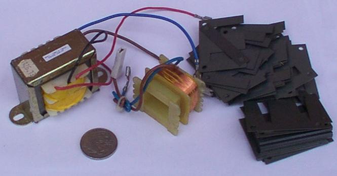
On left original transformer, right bobbin with secondary already removed and lots of laminations.
Heatsinks
The IRF510 and the uPC2002s will need to bolted to some sort of heatsink. If you use a metal case that will probably be adequate. Using a metal case is also good for keeping harmonics etc inside the transmitter and out of local TVs, CD and Tape Players. Small 'clip on' heatisnks may not be adequate, and I like to bolt anything in a TO220 case down to something solid. The tab of the uPC2002 is grounded, so you can bolt it straight to the case if that is ground. The tab of the IRF510 is live, so you will need to use inulating hardware to insulate it from ground. A silicon pad and insulating washer are fine.
Toroids
L2 & L3 are wound on T50-2 Toroids (red 0.5" diameter). L2 is 8 turns and L3 is 14 turns of 0.8mm wire. The wire gauge isn't really critical. L3 should be aproximately 1.1uH.
When winding toroids, the number of turns is the number of times though the centre of the toroid.
The inductance of a toroid can be varied somewhat by spreading out or bunching the turns. 'A' is 14 tuns on a T50-2 spread out over the entire core. This measures about 1.1uH. 'B' is 14 tuns on a T50-2 taking up about 1/2 of the toroid. It measures about 1.4uH.
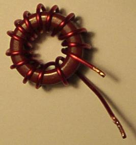 | 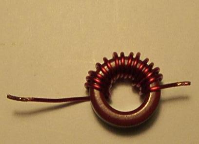 |
| A. T-50-2 14 turns 1.1uH | B. T-50-2 14 turns 1.4uH |
L2 should be adjusted as in the adjustement section below by spreading or squeezing the turns. Once its right you can stick them in place with clear nail varnish.
Misc Parts
C5 is a 175-680pF compression trimmer. In fact an Arco PC468

I just used a 'D' size xtal I had laying around.
Adjustment.
Adjust the the bias on the IRF510 to 0V. Disconnect power to the modulator. Connect a dummy load and fire it up. At this point the current drawn should be quite low, and power output almost non existent. Adjust the bias up until you see some RF out or the current goes up to about 1 amp. If there is no output with 1A of current, then the oscillator probably isn't oscillating. Fix it.
Once you can see some RF output, increasing the bias voltage will increase output and current to a certain point, then the RF level will be stable but current will increase. Back off to the level where the RF stopped increasing. Adj L2 and C1 for about 10Watts out at about 1.2-1.3Amps. This is sort of a balancing act. You can get more out, but the efficiency sucks. About 10 Watts seems about right. The adjustments will interact so keep tweaking. The peak in adjusting C1 is quite broad.
Reconnect the modulator. Adjust the pot so that that with no input the voltages on pin 4 of the uPC2002s are the same.
Applying audio should result in a modulated signal. If it doesn't you'll have to track down the problem. Under normal circumstances with no input, NOTHING in the modulator should get more than slightly warm.
Voltages
				DC
Gate of IRF510		        6.52V
Drain of IRF510		        13.3V
Antenna			        0V
Pin 1 of uPD2002		0.74V
Pin 2 of uPD2002		0.74V
Pin 3 of uPD2002		0V
Pin 4 of uPD2002		6.32V
Pin 5 of uPD2002		13.5V
The End
As I said previously, the modulation level drops off at around 100 Hz. It would be a good idea to highpass filter the audio into the modulator to remove low frequencies, to leave more headroom for 150-5 Khz. Don’t try to bring up the bass with equalisation. It will just result in more distortion. And guess what - not too many SW receivers have decent bass response anyway.
Have Fun
807
Some other possibly useful links
QRP's bunch of links to transmitter stuff
Dave Martin's 'Commando' high level modulation
Dave Martin's 'Corsair' low level modulation
Yahoo home brew pirateradio group