Analysis of the Weinberg Converter with Mismatched Turns Ratios
by Brad Suppanz
When the Weinberg converter uses the same turns ratios for it's
coupled inductor and transformer, it behaves just like a buck converter.
However, it is sometimes desirable to use different turns ratios
for the coupled inductor and transformer (for example, to lower the voltage
stress on the switches). This modifies the converter behavior, causing
it to take on characteristics of a flyback converter "blended" with a buck
converter. This paper studies the large-signal and small-signal converter
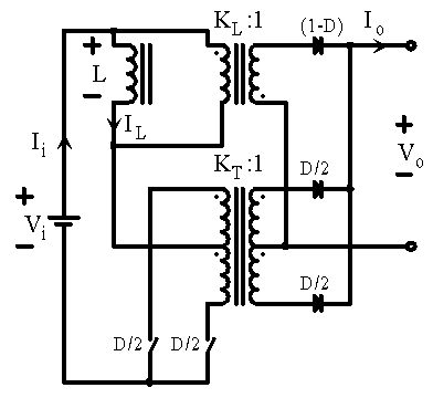
operation of the mismatched Weinberg. The schematic is shown in Figure
1 below. The inductance of the coupled inductor has been shown explicitly,
therefore the transformers are assumed to be ideal for the purposes of
this analysis.
 Figure 1. Schematic Diagram.
|
Notes on variables:
Bold Italic Capitol Letters = Large-Signal values (AC plus DC)
Capitol Letters = DC operating point values (and constants)
Small Letters = Small-Signal (AC values)
Large-Signal State Space Averaged Equations:
VL = (Vi
- KT*Vo)*D - (KL*Vo)*(1
- D)
(Equation 1a)
IL = KT*Io*D
+ KL*Io*(1 - D)
(Equation 1b)
Small-Signal State Space Averaged Equations:
vL = D*vi + [Vi + Vo*(KL
- KT)]*d + [D*(KL - KT) - KL]*vo
(Equation 2a)
iL = [KL - (KL - KT)*D]*io
- Io*(KL - KT)*d
(Equation 2b)
Define the mismatch parameter J as:
J = KL - KT
(Equation 3)
Therefore, in terms of J,
vL = D*vi + [Vi + Vo*J]*d
+ [D*J - KL]*vo
(Equation 2c)
iL = [KL - J*D]*io - Io*J*d
(Equation 2d)
Finding the Steady-State DC transfer function, Vo / Vi
Setting the steady-state inductor voltage and all the AC components to
zero in Equations 1a yields:
0 = (Vi - KT*Vo)*D -
(KL*Vo)*(1 - D)
(Equation 1c)
From this, we can get the steady state transfer function as follows:
Vi*D = KT*Vo*D + (KL*Vo)*(1
- D)
Vi*D = KT*Vo*D + KL*Vo
- KL*Vo*D
Vi*D = Vo*[KT*D + KL
- KL*D]
Vi*D = Vo*[D*(KT - KL)
+ KL]
Vi*D = Vo*[KL - D*J]
| Vo / Vi = D/[KL - D*J]
(Equation 1d) |
Note that when KT = KL
= 1 (and therefore J = 0), we get
Vo / Vi = D
which is what we expect for a buck converter.
Finding the Small-Signal transfer function, io/d
In addition to the state space averaged small-signal equations shown above
(Equations 2c and 2d), we have the following basic circuit equations:
vL = iL*L*s
(Equation 4)
vo = io*Zo
(Equation 5)
(where Zo includes the output filter capacitor and load
impedance)
vi = 0 (Equation
6)
Substituting Equations 2c, 2d, 5, and 6 into Equation 4 yields:
[Vi + Vo*J]*d + [D*J - KL]*io*Zo
= {[KL - J*D]*io - Io*J*d}*L*s
(Equation 4a)
Rearranging:
[KL - J*D]*[Zo + L*s]*io = [Vi
+ Vo*J + Io*J*L*s]*d
(Equation 4b)
Rearranging again, we get the transfer function:
| io/d = {Vi + Vo*J + Io*J*L*s}/{[KL
- J*D]*[Zo + L*s]}
(Equation 4c) |
Note that for KL = KT = 1, (J = 0), we get
io/d = Vi / [Zo + L*s]
(Equation 4d)
as for a buck converter.
Otherwise (when KL and KT are arbitrary) we get
a zero at:
Vi + Vo*J + Io*J*L*sz =
0 (Equation 7a)
sz = -{Vi + Vo*J}/{Io*J*L}
(Equation 7b)
This zero may be in the LHP or RHP since J may be plus or minus.
To find the conditions where the zero crosses into the RHP as a function
of J,
set the zero location equal to zero as follows:
sz = 0 when
Vi + Vo*J0 = 0
(Equation 8a)
or when
J0 = -Vi / Vo
(Equation 8b)
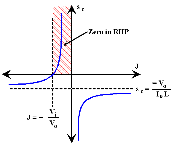
The position of the zero can be visualized by plotting sz
versus J as shown below.
 Figure 2. Zero location versus J.
|
So the zero is in the RHP when,
-Vi / Vo < J < 0
back to Switched Mode Power Supply Notes index
© Copyright 1997 Brad Suppanz. All rights reserved.
Links to this page are encouraged.
Email comments and suggestions to:

Sign My Guestbook
View My Guestbook
Written 10/8/97
Last updated 7/20/04
Number of hits: 


