Sampling Effects and Slope Considerations
by Brad Suppanz
This paper shows an example of using discrete time equations to study
the sampling effects for a boost converter with peak current control and
continuous conduction mode. The familliar stability boundary (d <
1 / 2) for peak current mode control without slope compensation will be
derived in terms of inductor current slopes.
Figure 1 below shows the inner current loop for the peak current mode
controlled boost converter. In general, the output voltage would
be controlled by the outer voltage loop. The output voltage is held
contstant here to analyze the current loop dynamics and is shown as a battery.
 Figure 1. Peak Current Mode Controlled Boost Converter.
|
Figure 2 shows the inductor current waveform. Note that IL(k)
is defined as the current at the beginning of a switching cycle.
During each switching cycle, the current starts at IL(k), then
move up to Ic(k), then down to IL(k+1). Ic(k)
is the "commanded" current. The nature of the circuit insures that
the peak inductor current will follow Ic(k) without any interesting
dynamics or ringing. However, IL(k) does exhibit
some interesting dynamics, so the transfer function from Ic(k)
to IL(k+1) will be studied.
 Figure 2. Inductor Current Waveform.
|
The slopes of the inductor current are as follows:
m2 = ( Vo - Vi ) / L
(Equation 2)
And times t1 and t2 are:
t1 = {Ic(k) - IL(k)} / m1
(Equation 3)
t2 = Ts - t1
(Equation 4a)
t2 = Ts - {Ic(k) - IL(k)}
/ m1 (Equation 4b)
Then, IL(k+1) would be:
IL(k+1) = Ic(k) - m2*t2
(Equation 5a)
IL(k+1) = Ic(k) - m2*[Ts
- {Ic(k) - IL(k)} / m1]
(Equation 5b)
Rearranging:
IL(k+1) = [1 + m2 / m1]*Ic(k)
- [m2 / m1]*IL(k) - m2*Ts
(Equation 5c)
Equation 5c has the form of an Infinite Impulse Response (IIR) filter with
an offset of:
Offset = m2*Ts
(Equation 6)
So, Equation 5c becomes:
IL(k+1) = [1 + m2 / m1]*Ic(k)
- [m2 / m1]*IL(k) - Offset
(Equation 5d)
It is helpful to draw a block diagram representation of Equation 5d as
shown in Figure 3 below.
 Figure 3. Block diagram representation of Equation 5d.
|
We can go into the "z-transform" domain by setting the "Offset" term's
AC value to zero and introducing the "z-1" delay operator:
IL = [1 + m2 / m1]*Ic*z-1
- [m2 / m1]*IL*z-1
(Equation 5e)
So, the transfer function is:
IL / Ic = [1 + m2 / m1]
/ [z + m2 / m1]
(Equation 5f)
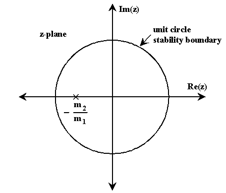
and the pole is at:
zp + m2 / m1 = 0
(Equation 6a)
zp = -m2 / m1
(Equation 6a)
Since m1 and m2 are defined as positive numbers (see
Equations 1 and 2), the pole will be on the left side of the real axis
of the z-plane as shown in Figure 4 below. For stability, the pole
must be inside the unit circle.
 Figure 4. Pole Location and Stability Boundary.
|
The condition for stability is therefor:
| m2 / m1 | < 1
(Equation 7a)
Then, from Equations 1 and 2:
( Vo - Vi ) / Vi < 1
(Equation 7b)
Or,
In terms of duty cycle (which is):
d = ( Vo - Vi ) / Vo
(Equation 8a)
the stability condition becomes:
d < ( 2*Vi - Vi ) / 2*Vi
(Equation 8b)
Or,
Thus, for the converter to be stable, the duty cycle must be kept below
1/2. Further study can be done by using Excel (or another spreadsheet)
to observe the step response of the transfer function (Equation 5f).
It is also useful to study the transfer function and loop gain in the s-domain
by using the delay operator " e-s*Ts " instead of " z-1
".
back to Switched Mode Power Supply Notes index
© Copyright 1997 Brad Suppanz. All rights reserved.
Links to this page are encouraged.
Email comments and suggestions to:

Written 9/17/97
Last updated 7/20/04
Number of hits: 


