The Crankshaft
The critical objective with any crankshaft is to ensure that the crank pin and the main axle are parallel in all directions. If this is not the case there are all sorts of awkward twisting actions applied to the connecting rod causing tight spots and binding. The other dimension to get right is the linear distance between the crank pin and the axle as this defines the stroke of the engine.
During the building of my
Stuart No 10 engine I had several failed attempts at building a crankshaft and so the method described may seem over the top, but it was my attempt to get things right first time.A crankshaft can be made in many ways, it can be :
The Stuart No 1 plans, call for a crankshaft which is made from bar stock but due to the trouble I had building my Stuart 10 crank in this manner, I decided that I would build the crank oversize and then machine it true on the lathe as though it were a casting. On reflection I think this was excessive and in fact, when I had completed the fabrication of my crankshaft it was true enough to be used without machining, had it not been made oversize.
Anyway, on with the machining.
First the main axle was cut to length and so was the crank pin. Both were faced square in the lathe and the axle was set to run true in the 4 jaw so that it could be centre drilled accurately in both ends.
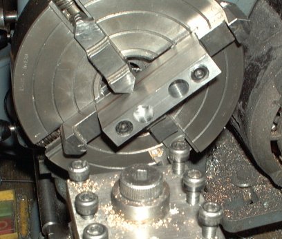
The crank webs were machined next. The two parts were screwed together to ensure that they would be a matched pair and then the 2 holes were bored using the 4 jaw chuck on the lathe to get them exactly parallel.
Boring the 2 crank webs
When this was complete the web were cut to length using a hack saw, removing the securing screws in the process.
Then the rods and webs were assembled and cross drilled in the drill press to allow pins to be used to hold the assembly together. Both crank webs were clamped together in the drill vice to ensure that they were pinned in line with each other.
Bear in mind the final layout of you engine at this point. You can have extra axle material sticking out of the flywheel side or the eccentric side (or both) to be used as a power take off point for the engine. Where you pin the webs effectively defines the position of the axle through the engine so if you need the power take off on the flywheel side now is the time to set that up. I chose to stick to the drawing which defines a flush fit with the flywheel on one side and the power take off on the eccentric side.

Drilling and pinning the crank webs to the rods.
Next there was a choice to either 'Loctite' the crank together or silver solder it. I chose the latter method as I felt it would make a stronger joint. If you silver solder the crank as well, then let it cool slowly in the hearth so that it doesn't harden and doesn't distort.

The crank after soldering.
Next I mounted the crank on the lathe between centres and turned the crank webs to their final thickness. I also turned the radii on one end of the webs. I used a drilled block of bright mild steel to drive the crank round. I didn't have any right handed tools so I turned the assembly over to machine the second web.
SAFTEY NOTE
: I had been using a single jaw in my 3 jaw chuck to drive the crank driving block round. However during this machining the jaw flew out - no harm done this time but something to be avoided ! I think the intermittent cut of the crank webs had rattled it loose. Anyway If you have a proper driving plate then use that. I future I will use a cable tie to hold the jaw in place and also make regular checks to see if it has moved.|
Machining the crank webs to size. |
The crank after the first stage of machining. |
Also in this setting the reduce diameter section of the axle was turned to size.
The next process was to remove the section of the axle between the webs and then machine the inside faces of the webs. To do this 2 blocks of bright mild steel were drilled to hold the crank axles and also a hole 1 inch from the first hole to act as a centre to turn the workpiece. The radii on the other end of the crank webs were also cut in this setting.
In my opinion this is a ghastly set up, there is loads of metal flying round and great care had to be taken to ensure that obstacles were not in the way. Very light cuts were the order of the day to avoid the workpiece moving.

Machining the other end of the webs and the inside faces.
I was also hoping to turn the crank pin to it's final size to ensure it was true with the axle but unfortunately the run out (caused by the fact that the holes in my mounting blocks were not exactly the same as the crank throw), would have meant that the crank pin would have finished considerably undersize. If I were do to this again I would use an oversized crank pin to start with which could then be bought into true and still be the correct final size. Anyway although the crank pin appearance was not great after the soldering I decided that it was true enough and just cleaned it up with some wire wool.

The Finished Crank.

