Patriot UPS to Windows 2000 configuration
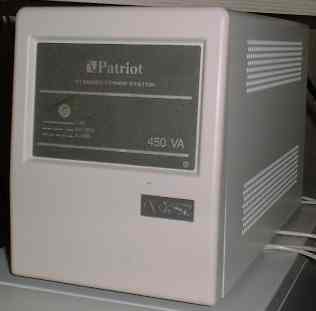
I rescued a Patriot UPS from the dumpster.
The only problem was a dead
battery. I found a battery that was the same size
and rating. After the battery was replaced the UPS
started working. This UPS has a "dumb"
serial interface. It uses the control lines on the
interface to indicate power loss and low battery.
Windows 2000 has a built-in UPS service. The problem was identifying which pin on the serial interface Windows was monitoring. I searched the web for serial UPS pinouts. I tried a few out on my Win2K box.
Windows 2000 has a built-in UPS service. The problem was identifying which pin on the serial interface Windows was monitoring. I searched the web for serial UPS pinouts. I tried a few out on my Win2K box.
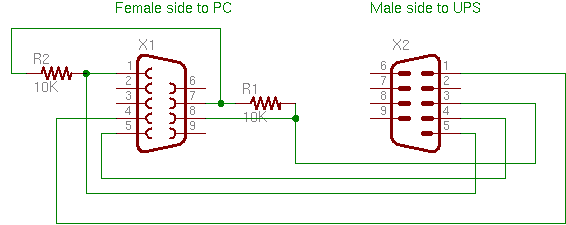
Here is the cable pin out
Schematic of the UPS cable
Windows 2000 software configuration
Next click
the Select Button.
Choose Generic for the manufacturer, click on
Custom, select the com port the UPS is connected to, and then click the
Next button.
Choose the com-port which will connect to the UPS.
Choose the com-port which will connect to the UPS.
Click the Next.
Click the negative radio buttons for the
Power Fail/On Battery and the Low Battery signal polarity. Then click
the Finish button.
Next click the Configure button.
Configure the UPS software response as shown.
Then click OK.
Finally Apply the changes by clicking the
Apply button. The power management software will begin
monitoring the UPS.