SeGuruCool
The Largest Independant Solid Edge Resource Outside UGS

SeGuruCool The Largest Independant Solid Edge Resource Outside UGS |
|
www.oocities.org/SeGuruCool  segurucool @ indiatimes.com segurucool @ indiatimes.com |
|
|
|
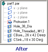
Limitations in the Solid Edge Oject Model The Solid Edge Object Model has some limitations at a very basic level. Although, the online documentaiton comes with plentiful VB code, these are not worked out examples - they are mere code snippets that show you the way to an object/method/property down the heirarchy. To add to the misery, the documentation does not appear to be updated as and when the Solid Edge Object Model changes. This forces you sometimes to give up an idea for customization. I wanted to create a utility that traverses the features of a part file and renames the Hole features to something meaningful i.e. Hole_1 which is a simple hole is renamed to Hole_38_Dia Hole_2 which is a Threaded hole is renamed to Hole_Threaded_M12 Hole_3 which is a CounterBored hole is renamed to CBore_26x42Deep and likewise... (see figure below)   |
|
Cannot Rename Features in Solid Edge Coding this was easier said done than done. I could extract all information for a hole : 1. Connect to the Application Bone 2. Connect to the PartDoc Bone 3. Get the Holes Collection Bone 4. Get the Hole Object 5. Get the HoleData I also got the Name property for the Hole. Once I collected all the information from a hole, it was time to change the Name property for a hole. The following code : objHole.Name = "CSink_" & objHoleData.HoleDiameter & _ objHoleData.CountersinkDiameter & "x" & _ objHoleData.CountersinkAngle & "Deg"greets you with this message :  |  |
|
I also customize SolidWorks and Inventor using VB. Renaming features is possible in these competing MCAD programs. In SolidWorks, the syntax is : objPart.SelectedFeatureProperties 0, 0, 0, 0, 0, 0, 0, 1, 0, "CBore_26x42Deep"where, objPart object of SolidWorks is the equivalent of the Model object of Solid Edge. In Inventor, the syntax is : objPart.HoleFeature.Name = "CBore_26x42Deep"where, The syntax is self Explanatory. Also, the HoleTapInfo object of Inventor is the equivalent of the HoleData object of Solid Edge. |
|
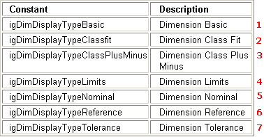
Undocumented Properties and Type Constants The DisplayType property for a Dimension object is not documented. It should have been at the position shown by red arrow in the figure below :  The AutoList members option of VB displays the DisplayType property for a Dimension object :  Again, in the documentation, igDimDisplayBlankType is cooly missing in the DisplayType constants list. Count the red number in the figure above and then below.  |
|
Ordered Geometry - DisOrdered Documentation The internal structure of the OrderedGeometry object is undocumented. The Profile object is very common in most Solid Edge features. It represents the sketch for all protrusions, cuts, etc. objProfile.OrderedGeometry(numelements:=lngNumGeometry, Elements:=objGeometry)Here, lngNumGeometry is a Long variable, but objGeometry is merely an object variable. As a result, the variable for objGeometry follwed by a dot does not produce any AutoList of its members. In fact, you can actually compare it against ObjectType constants, using the following syntax :
For i = 0 To UBound(objGeometry)
  If objGeometry(i).Type = igLine2d Or igArc2d Then
    objGeometry(i).GetStartPoint(LXS, LYS)
    objGeometry(i).GetEndPoint(LXE, LYE)
  End If
Next
But, this is all by intutiion.
|
|
Solid (Blunt) Edge I have a model as shown in figure below.  In Solid Edge, rounding all six edges produces a geometry as shown in the figure below.  This does not match with the results of actual machining. But rounding it using AutoCAD, yes, the scornful, underestimated, 2D Drafting program - AutoCAD does this gracefully. It produces a star shaped complex surface as shown below :  This matches with the surface produced by actual machining of the part. Further, I copied the surface in AutoCAD using the Copy Face command, mapped a small black-and-white stripped bitmap created using the humble MS Paint. This revealed the complexity of the AutoCAD created surface as shown below :  Solid Edge has the zebra-strip facility : built-in, but whats the use if the surface is not in place ! Download Cobbler.zip (74 kb) - file containing SE 14 part file, ACAD 2000 file and the zebra-strip bitmap. |
Tushar Suradkar  segurucool @ indiatimes.com segurucool @ indiatimes.com |