
SeGuruCool
The Largest Independant Solid Edge Resource Outside UGS
|
SeGuruCool The Largest Independant Solid Edge Resource Outside UGS |
|
www.oocities.org/SeGuruCool  segurucool @ indiatimes.com segurucool @ indiatimes.com
|
|
|
|
It is strongly recomended that you first complete the FEA basics tutorial, where you learn in-depth the theory behind : |
|
In this tutorial, you learn the following: |  |
|
Problem Description The problem is to model and analyze a model of a bearing assembly. The bearing assembly consists of a pillow block housing and a bearing insert. The bottom surfaces of both parts are are bolted down. A shaft is fitted through the bearing insert, which allows the shaft to rotate. The shaft can exert pressure in several directions and we will examine the forces in downward direction only. | 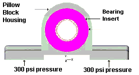 |
|
Starting Solid Edge Start Solid Edge and open or create a bearing assembly as shown in figure. Small features such as fillets, etc are of no consequence to the results of the finite element analysis. |  |
|
Adding the ALGOR menu and toolbar Select Tools > Add-In Manager. Click ALGOR in the list such that the check mark is present. Click OK. The ALGOR menu and toolbar should appear. |  |
|
Generating a finite element mesh In Solid Edge, select Algor > Mesh The CAD Solid Model environment opens. In the lower-left corner of this window, notice the messages that read Beginning CAD data import... followed by Rendering part (1 of 2)... and Rendering part (2 of 2)... When the message reads Ready, select View > Enclose. The solid model should look as shown in figure. |  |
|
Adjusting the display Select Window > New Window and then, Window > Tile Horizontally and finally View > Display > Features This displays the model in multiple windows as shown in figure. |  |
|
Hide the bracket Select Pillow Block.par:1 in the model tree and select visible from the menu. This will hide the pillow block housing. |  |
|
Create Surface Mesh Select Mesh > Create Surface Mesh. Set the mesh size half-way between Coarse and Fine. Click the Mesh button. The model is meshed as shown in figure. |  |
|
Transferring to the FEA Object Editor Select Tools > FEA Object Editor. The FEA Object Editor loads the mesh in to ESX database. |
|
Specifying Analysis Type Select Analysis > Parameters. On the design scenario toolbar, set analysis type to Linear Static Stress |
|
Specifying Element and Material Property Click on the pillow block housing and right click on it. From the menu that appears, select Modify > Materials Under Select Material, pick Cast Iron Click OK to accept the material information and close the Element Material Specification dialog. Similarly, apply Steel to the bearing insert. | 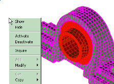 |
|
Adding a pressure load Select View > Orientation > XY Bottom Select Selection > Select > Surfaces Using the control key, select both the bottom surfaces of the pillow block housing. Right click and choose Add > Surface Loads Under Normal Pressure, specify 300 for Pressure. |  |
|
Adding Boundary Conditions Select View > Orientation > Isometric. Click on the surface of the bearing insert hole. Right click and select Add > Surface Boundary Conditions. Under Predefined, click Fixed and then OK |  |
|
Checking the model with SuperView Select Analysis > Check Model. SuperView starts and after verifying the model geometry and the finite element data, the assembly will appear in the SuperView display window. |  |
|
Analysis and PostProcessing Select Analysis > Perform Analysis... . Click the analyze button. After the analysis is over, select View > Results. Select Results > Displacement Data > Displaced Model. Click on Displaced Model ON |  |
|
Display Stresses Select Results > von Mises Stress. Select File > Save Image As. Click the list Save as type at the bottom of the save dialog and select .jpg Select File > Exit. |  |
|
Tushar Suradkar segurucool @ indiatimes.com |
 Download FREE 6 chapters & source
code
Download FREE 6 chapters & source
code