Better Half VW Builders
Log
This is a log of the process while building my
½ VW engine. I used a combination of two different sets of plans. Leonard
Millholland’s Better Half VW and Scott Casler’s Hummel Engine plans. Most of
the parts were bought through Hummel Engine. I was going to try all of the
machining myself but decided to buy the major components instead.
I started out by buying a well used VW engine
thinking that I could use most or at least some of the parts to save money.
After tearing down the engine, I realized that most of it was just a big pile
of junk and the only thing that was useable would be the engine case.

I took the case down to my local
I
made the rear cylinder blank off plates out of 2024T3 aluminum. I first made a
cardboard pattern then traced it over to the aluminum and cut it out with my
jig saw and finished them off with a hand file.
![]()
![]()

Next was making the cover plate that blocks
off the oil cooler line holes. This was done also by making a cardboard pattern
and tracing it on to a 3/8 piece of 2024T3 aluminum. This is a little thicker
than the plans call for. After talking with Steve Kiblinger, this was needed
due to the high oil pressure going through the small area.
Next was making the rear cover plate that blocks
off where the rear main bearing goes. I spaced the hole for six (6) ¼” coarse
thread bolts.

Instead of making two plates that block off
the unused rear push rod holes, I drilled and tapped the holes with a ¾” NPT
pipe tap. I used a big drill press in the EAA”s restoration shop for this
process. My press was not big enough. It was quite a chore to hold down the
case and tap at the same time. I bought four (4) ¾” pipe thread aluminum plugs
from McMaster Carr Supply Co. down in

After
most of the plates were made it was time to modify the case. The case is a
Model “AJ” which is a suitable case for our modification. Turns out to be from
1975.
After
bolting the two case halves temporarily together, I held the rear plate that
blocks off the rear bearing to the back side of the engine and marked where the
six (6) holes will go. Then I unbolted the engine halves and drilled and tapped
the holes with a ¼ course thread tap.
The oil passages that lead to the rear of the
engine were blocked off by using the rear plugs on the back side of the oil
galley. I used a thin brass punch to drive the plugs through the oil galley,
then picked them up with a small pair of pliers and tapped them in place
between the two lifter bore passages. After this was accomplished I drilled and
tapped the rear plug areas that were removed with a 5/16” tap and secured the
holes with 5/16 allen set
screws.
![]()
![]()

I did one more modification to the case that
was recommended by another builder that had a problem with his distributor
moving from the timed position he set while in flight. This modification has
you drill and tap a set screw on the front side of the case in front of the
distributor.
It’s
called a grub screw. The placement of the hole is measured down to where the
rubber grommet seal is between the distributor shaft and where the drive gear
is. This set screw is snugged down once the engine has been properly timed.
This screw rests on the rubber grommet seal which holds the distributor in
place in case the normal hold down device should loosen.


After all of the work that I could do was
finished, I boxed the engine case up and sent it over to Hummel Engines and had
Scott Casler modify the case for his 92MM cylinder set up and a 78MM crank
balance assembly.
Like I mentioned earlier, I was going to try
all of the machining my self but just don’t have the tools to do this type of
work. Next time I will try the head conversion my self though. The heads that
came off of the original engine are actually in pretty good shape. I think I will
practice on them and if they come out I can use them as a spare set if needed
in the future.
While Scott Casler had the case, I ordered the crank, heads, bearings and a prop hub and had him ship it all back at the same time. I must add that Scott does an excellent job on the heads!!!


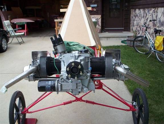
Next
it was time to dry assemble the engine to make sure it all fit. I bought the
.009 Bosch distributor and a VW seal kit from Mofoco down in

I
started the assembly by putting the distributor in first along with the
required shims. I guess I won’t go into great detail of how I put the engine
together but will say that I pretty much followed the “Great Plains aircraft
Type 1 Engine Assembly Manual” to a tee. Between that and the other recommended
“How to Rebuild Your Volkswagen Air Cooled Engine Manual”, the job went pretty
smooth.

I bought two 26MM Mikuni Carburetors from
Central Snowmobile Salvage. Also purchased were two spigot mount rubber flanges,
dual throttle cable and a choke cable assembly. I tried to find two 28MM
carburetors but none were to be found. Used that is. The guy behind the counter
who was also a mechanic said the 26MM carburetor has the same body that the
28MM carburetor uses and said that if the 26MM throat size was not effective I
could take it to any reputable machine shop and have them drill the opening out
to a 28MM size.

After the engine was complete, I made a set of
cooling tins to direct more air over the heads and cylinders out of cardboard,
once satisfied with the shape I transferred them over to a sheet of .025 2024T3
aluminum and cut them out with a pair of tin snips. I finished them off with a
smooth hand file.

At this time, the engine has only one hour of
run time, It runs great with the two 26MM carburetors.
There were two small oil leaks that have since been fixed. I am getting
approximately 3150 static