|
Morphology is the study of structure in images. It is based on the concept of
transforming images by probing them with smaller images known as selective elements.
The two fundamental morphological operations are erosion and dilation.
In the case of erosion, the objective is to see how the smaller image fits within
the larger image. In the case of dilation, the objective is to find the union of
the smaller images with local regions of the larger image. Using different combinations and permutations of erosion and dilation, aggregate operations (macros) can be performed. The two most common are opening and closing. Incorporating other operations such as union, intersection, complement, and subtraction, operations such as 'hit and miss' and 'skeletalization' can be performed. One very significant advantage of morphological processing is the ease of implementation. Due to the fact that the operations are simple and local, they can easily be implemented in hardware as well as software. Since the number and length of interconections between pixel cells increase with the size of the selective element and most selective elements are small (usually between 3x3 and 15x15), the hardware is not complex. The following figure shows erosion and dilation with respect to a solid 3X3 selective element. In the first original image there are three places where the selective element fits; i.e. where the selective element is contained in the local region. The second original image is the result of the erosion of the first image. Here there are only three active pixels. Dilation is performed by centering the selective element over each active pixel and taking the union of the two. 
Erosion
To achieve erosion, the output must be true if either the weight
is false (don't care) or the pixel is true. The output should
only be false if the weight is true and the pixel is false. This
logic function is shown below:
Using a NAND gate and an inversion of the pixel value before it
enters the NAND gate, the desired output can be constructed: 
Dilation
To achieve dilation, the output must be a simple AND of the pixel and the weight:
Using a NAND gate and an inversion, the desired output can be
constructed:
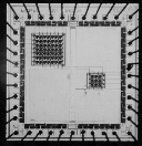
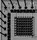
Schematic of one pixel in the array The chip was fabricated in a standard 2-micron n-well double-metal, double-poly ORBIT process. Several microphotographs follow:
Pinout
Results of the 3x3 array: The 3x3 was tested with MorphView and works without errors. This result
is due to the fact that the array is small enough to be loaded and
the output taken before the capacitors have time to discharge, even
with very slow communications. The tests were performed on a DX4-100
(486) personal computer running WINDOWS 95.
The 3x3 was tested with MorphView and works without errors. This result
is due to the fact that the array is small enough to be loaded and
the output taken before the capacitors have time to discharge, even
with very slow communications. The tests were performed on a DX4-100
(486) personal computer running WINDOWS 95.Results of the 7x7 array: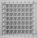 By itself, the 7x7 array cannot always be loaded and the output taken
before the capacitors discharge due to the fact that communication with the PC is
too slow without pipelining or kernel mode programming.
By itself, the 7x7 array cannot always be loaded and the output taken
before the capacitors discharge due to the fact that communication with the PC is
too slow without pipelining or kernel mode programming.The figure below shows the dependency of noise on loading time. In each image, the ideal image is all white, but due to the fact that the chip was not loaded within a predefined time, there is noise.  These images show the consequence of loading the chip and taking the output at increasing cycle times. Going from left to right, the processing times were 240, 420, 600, 780, 960, 1140, and 1320 microseconds. Notice that as the processing time increases, the probability of making an error on a given pixel increases due to discharging capacitors. Notice that in the first image, there are no errors. But as soon as the cycle time increases to 420 us, a small amount of noise appears. As a result, the chip needs to be loaded and the output taken within 240 microseconds or less. Due to the fact that the parallel port communication routines are limited to sending or receiving only 1 byte every 60 microseconds on a 486 DX4-100 PC, there is a need for pipelined interface circuitry and on-board non-overlapping clocks to decouple the chip from the computer. This circuitry consists of 138 decoders, PLDs, and static CMOS RAM, and allows the software to only send out 1 byte in exchange for 1 bit instead of sending out 21 bytes in exchange for 1 bit (3x7=21 due to non-overlapping clocks being implemented in software).
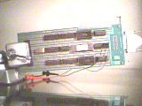
Demo board with pipelined control logic and parallel port interface to the 7x7 array.
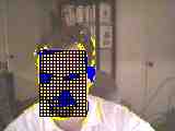
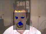
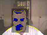
Demo video of realtime morphological closing of motion. Dilation followed by erosion filters out stray motion energy and allows the ROI tracking algorithm to correctly place the grid over the face: |
||||||||||||||||||||||||||||||||||||||||||||||||||||||||||||||||||||||||||||||||||||||||||||||||||||||