
The Boiler Cell
By Mike Johnston
Copyright © 2003
I have been posting reports on this effect to various lists for some time now. This is the first time however that I have tried to put together a paper on it. This is because I don't have a complete explanation for what is going on within the cell and so can draw no final conclusions about it. I can only speculate or offer theories as to these causes and encourage anyone who wants or is able to perform the tests that would be required to obtain answers to these questions to do so. I will describe the materials necessary for this cell and the process to set it up. Then describe an initial “run” and a subsequent “run” and finally I will draw what conclusions I can from it.
The first time that I noticed this effect was when I decided to try using AC electricity to power an electrolysis cell. I hooked a cell that I had been running at 12 amps of current using a 12 volt DC power source up to a 120 volt AC power source and promptly blew a circuit breaker. That lesson learned, I set up a new cell without any electrolyte in it. I then gradually added electrolyte, just until a few tiny streams of bubbles began to form, and stopped to watch the cell. In a fairly short amount of time I noticed steam coming from the top of the cell. I let it run and soon the cell was boiling merrily. This started my research into the anomalous heating effect caused by my setup.
Above is an illustration of the basic setup. The power source (a) is 120 volt 60 hertz AC. The “standard” type of AC provided by the power company. The “hot” wire runs through a standard on/off switch (b) to the cathode of the cell (c ). The electrodes ( c and d) are both made from sheet stainless. A highly polished stainless works best, such as 316L or something similar. It should be as thin as is practical and sized to fit your container. I am using a one quart glass container (Pyrex would be best) and so my electrodes are about 5” long and 2” wide and separated by about 2”-3”. Having them any closer together could create the potential for arcing between the two. After doing tests with various sizes of electrodes I have decided that indeed, size does matter. So as large (in surface area) as possible will give you the best heating results.
The electrodes are inserted into the cell and clipped to the sides at the top so as not to shift while the cell is running and potentially short out by touching each other. Also please take a look at Sam Barros' website at http://www.powerlabs.org as he has done some interesting work with high voltage water capacitors. It would be advisable to do this if you are thinking of doing this experiment other than how I describe it here.
The Anode (d) goes directly to ground (g) in the breaker box. There is a 10 amp circuit breaker between the Anode and the ground and a 20 amp breaker in the breaker box on the switch side. The only other component illustrated is a thermometer. I have been using a stainless steel “meat” thermometer. A digital would probably be better with a high end of at least 300 degrees farenheit. The one I am using only goes to 180 degrees so I can't be precise but the boiling is obvious.
I have been using tap water in the cell. My water has two main impurities; Iron and Lime. It should be run with distilled water to make sure that the effect is still the same. I think it will be though. The electrolyte I am using is a combination of NaOH and KOH which is mixed in water at a concentration of 25% electrolyte to 75% water. It comes in a yellow one gallon container with a black plastic cap. It is made by Scotch and available in Wal-Mart.
Once I get everything set up, but before adding the electrolyte, I plug the unit in and turn it on. If all of the components are clean and reasonably pure water is used there should be no obvious reactions going on in the cell. I have left such a unit turned on for over an hour with no noticeable changes in that time. If you want to use electrical test equipment such as an ammeter and a current clamp I recommend getting them in place before turning on the power. If using a current clamp I recommend placing it away from the unit itself as the water in the unit will intensify the magnetic field to some extent due to it's paramagnetic nature and could affect the current reading if it is too close to the cell.
A modification that I should mention here is the addition of some type of resistor into the above circuit. The resistor being inserted between the cell and the ground. I did this initially because I was trying to limit current flow through the cell by outside means. In the end I decided to limit current by using a low electrolyte concentration instead. I did made some observations however while utilizing the external resistor that I think deserve mention. The resistors that I used were simple light bulbs. I started wit a 100 watt bulb. This allowed a current of about .4 amps to flow and the bulb lit normally. I then tried using a large infrared “heat” lamp like the ones used in restaurants to keep food warm. With this lamp current was reduced to near nothing due to its much greater resistance and the large filament of the heat lamp barely glowed.
The first thing that I noticed was that, especially with the much higher resistance of the heat lamp, was that the heating process took longer. On the other hand by including the high resistance the reactions within the cell during the charging phase were limited almost totally to the cathode. Bubbles were forming in normal quantity and size at the cathode but almost no bubbles were formed at the anode during the entire charging phase. This ability to limit the reactions within the cell to one electrode would seem to support the idea that very little energy from the power source is actually being used in the heating process. So essentially the current flow through the circuit is being limited by the resistor but the reaction at the cathode surface is not being so limited. This could be seen as an argument for the theory that the reaction is producing H2 and O2 gases from the water and then recombining them as mentioned below but if this is the case then by having the reactions limited to one electrode would seem to show that the amount of gas produced and then recombined at that electrode is not being determined by the circuit current and so prevents Faraday's Law from being applied in this situation. So the heat produced by the recombination reaction would not necessarily be equal to the amount of electrical energy being supplied in the I2R power used formula.
When the cell is set up and turned on with only water in it the time has come to add the electrolyte. The idea is to find just the right electrolyte concentration so that the heating effect is maximized with the least amount of actual current flowing through the cell as possible. I have determined that the optimum amount for my conditions is between 15 and 20 drops. Although I will mention that, once past the initial “charging” phase you can see heating with only one to three drops of electrolyte even if you empty the container, rinse it out and refill it with fresh water. I add the electrolyte solution with a plastic dropper. If it is your first attempt you should go slow and add only one to two drops at a time. I like to have a strong light source suspended over the cell so that I can watch what is going on inside pretty closely. After several drops you will see bubbles starting to form at the electrodes, especially the cathode. It may even be exclusively at the cathode if a resistor such as the high resistance lamp described above is being used. The bubbles at the cathode appear to be normal electrolysis bubbles at this point in quantity and size/behavior. These bubbles will only appear briefly and then disappear until you achieve the minimum amount of electrolyte in the cell where the bubbles will continue to be produced. As I said this is usually between 15-20 drops.
Once you are at the correct level of electrolyte just sit back and observe. For some reason the first run with this cell takes the longest to heat up. All subsequent runs heat up much faster. The reasons for this disparity I believe is the secret to how this cell heats water as fast as it does. For example, just to be sure I set up a fresh cell just as described above. I even made sure that I used hot water in it at 100 degrees farenheit. I had noticed previously that an established cell can heat the quart of water from 80 degrees to over 212 degrees in about 90 seconds. So I wanted to see the time if I started it with hot water. The time with the fresh cell to come to boiling was about 15 minutes. Once you get it to this point allow the cell to boil for a while. Depending on the size of your electrodes the cell may reach a point where it is advisable to shut it off as the water is boiling so fiercely that it threatens to explode right out the top of the cell. I call this the “Super Boiling” stage. Once my first run cell had reached boiling and been allowed to boil for about 30 minutes (I was using small electrodes so it never reached the Super Boiling phase) I switched it off to allow it to cool.
An interesting thing to see here is how the boiling in the cell responds to the on/off switch. As soon as you turn the power off all boiling in the cell stops, immediately. Then, if you flick the switch back on, the boiling recommences instantly. If you allow the cell to cool back to 80 to 100 degrees and then flick the switch on it will heat VERY rapidly back to boiling. It can go from 80 degrees to boiling in about a minute. The potential exists to heat even faster as I was heating the water from the top down due to the length and position of my electrodes and, since heat rises, it therefore took longer to heat that way than if the electrodes were inserted from the bottom of the cell and so were heating from the bottom, up.
The bubbles produced while the cell is boiling are not at all like electrolysis bubbles. The boiling bubbles are large and numerous and appear only at any sharp edges or corners of the electrode(s). The boiling bubbles also seem to be repelled away from the electrode as they rise whereas electrolysis bubbles seem to cling close to the electrode as they rise. I should note that it isn't the electrode metal becoming hot due to resistance that in turn heats the water either. The electrode metal actually seems to remain a few degrees cooler than the water in the cell. I should also mention though that the heat produced is all coming from the area right at the surface of the electrode. This is visible as heat waves coming from that area and radiating out into the rest of the solution.

The heating is so fast that you can actually watch the needle on the thermometer rise. This heating occurs at the same power level as the electrolysis that was observed when first setting up the cell (in the range of .5 amps or less). Adding fresh water to the cell as it is boiled off does not seem to affect the rate at which the heating takes place either. Once I had this much data on the cell and what it took to replicate the effects that I had originally noticed I began to consider possible causes for this seemingly anomalous heating of the water. The first thing that came to mind was simple dielectric heating akin to what is commonly used to heat water in a microwave oven. The problem with that is that we are using a frequency of only 60 hertz here and microwaves use in excess of 1000 kilohertz. Water molecules are supposed to be “transparent” to any heating effect by such a low frequency charge. And besides it doesn't heat equally in all situations. Remember that the first run takes substantially longer. That would imply that a substantial change must take place in either the metal of the cathode or in the structure of the water before the heating effect can be seen.
The next thing that I considered and the reason put forth by several Physicists on the Web was that anomalous heating in AC electrolysis was being caused by the water molecules being separated into both H2 and O2 gas at each electrode instead of having H2 produced at the cathode and O2 at the anode. Then, they theorized, these gases are almost immediately recombining with each other with the expected release of heat probably timed to the frequency of the supplied charge. While this sounds good at first there are some problems with it but also a benefit if it were to be true. On the one hand, if true, then it would mean that 100% of the energy being released by the combination of the H2 and O2 is being captured by the water in the cell and converted to usable steam. In other words near 100% efficiency with no pollution. Not too bad. The problem with that idea though is that it would mean that there could be all of this energy being released with a near zero current through the circuit. Why? Because the electrons necessary to turn the released H+ ions into hydrogen atoms at an electrode would already be available from the OH- ions at that same electrode and so the whole 2H2O ---> 2H+ + 2OH- --> 2H2O would be taking place without picking up or releasing electrons from or to either electrode. So you would have all of this wonderful thermal energy being released without the input of any (or very little) energy from your power source.
In other words the cell itself would be acting like a capacitor with perhaps a small amount of leakage and by setting it up slightly differently you could be using nearly zero power as almost everything put out by your power source would be returned to it. Perhaps setting it up like an LC circuit would be the way to go;

I haven't done the above configurations yet but do plan to as soon as I can get around to it. The third one (far left) is the LC configuration that is usually shown in books to illustrate how almost all of the power being provided by the power source can be returned to it. In such a case there would be almost no current through the cell and all of the heat energy generated would be a sort of “bonus” to the normal operation of the LC circuit. The AC power source could just as easily be a DC power source such as solar or a small alternator or magneto which is hooked up to an inverter and thereby changed to the required 120 v 60 HZ AC signal.
As I said though there are reasons why the recombination of H2 and O2 might not be what is causing the heating, or only part of the reason for it. Another possibility is that there is a transmutation reaction happening either in the solution at the electrode or within the electrode metal. Another name for such transmutation reactions is “fusion”. I like the term Electrochemical Fusion rather than Cold Fusion due to the negative publicity that Cold Fusion has received over the years. There is quite a bit of evidence beginning to emerge from various sources regarding this effect. It seems that certain metals such as Palladium and Nickel can be “loaded” with hydrogen. I considered this as a possibility. Once the hydrogen atoms or ions at the cathode are drawn into the metal lattice they could undergo fusion within the metal lattice if two or more were pulled in together. This would be more apparent if you were to use Deuterium or Tritium enriched water. This seems to have been confirmed to some extent by the analysis of electrodes used in similar experiments. These tests have shown metals included in the electrodes after the experiment which were not present before the experiment. See links to several papers documenting this effect at the end of this paper.

The above illustration depicts the process by which I think that H+ ions might get drawn into the metal lattice. The large circles on the left side of each picture represent the atoms of the electrode metal. The red lines between the metal atoms represent the electrostatic field that holds them together. I look at it as a kind of energy membrane. In the first picture we see the electrode having a positive charge. The free electrons between the metal atoms are being pulled back toward the power source and this causes the electrostatic field between the atoms to distend as well and also be pulled back toward the power source. This creates a tiny pocket or energy vortex into which the hydrogen ions (nuclei) are drawn as they follow the negative energy to which they are attracted back into the metal.
To the right of the metal atoms in each drawing are the chains of water molecules which form along the electrostatic lines of force that exist between the electrodes. These lines of force are represented by the red lines above and below the water chains. The black dots connected to some water molecules are neutrons and along with their associated proton, represent Deuterium ions. In the second picture we see the electrode charge switch back to negative, forcing the free electrons back toward the electrode surface and by doing so distending the field between the metal atoms in the opposite direction. This has the effect of trapping the hydrogen ions from the previous positive cycle inside the surface of the metal. On the next positive cycle more hydrogen ions are drawn into the metal and once inside they are met with the hydrogen ions that had previously been pulled in. If a Deuterium ion is pulled in there can be a fusion reaction between it and the waiting proton (hydrogen ion). This fusion reaction releases a substantial amount of heat. It is interesting to consider the possibility of the effect being a tiny energy vortex or whirlpool because at the sizes involved (inter atomic spaces) the kinetic energy inherent to such a vortex would be enormous. It could then add to the energy required for the fusion reaction to take place or possibly aid in the formation of neutrons. Once all of the spaces between the electrode metal atoms have been filled with hydrogen atoms/ions the metal is said to be “loaded” and it is at this point that I think that heating commences in earnest.
Another interesting thing that can be seen is that the gases which are exiting the cell , once it reaches the boiling stage, are not flammable. In fact, they will extinguish the flame of a match or a butane lighter when it is held directly in the stream of exiting gas. Whether this is due to the presence of a high percentage of steam in those gases or to there being some other inert gas such as helium mixed in is not clear at this point. The analysis of those gases would shed a great deal of light on the reaction(s) that are taking place within the cell. Another test would be to analyze the metals of the electrodes both before and after the reaction.
In any case a potential application for this cell would be to use it as a boiler to produce steam for some purpose. Below is a rough diagram of what such a boiler would be like;

While experimenting with this effect I set the cell up in several different ways and made some modifications just to see the effect that would be achieved by doing so. In one experiment I set up three of these cells in series. In that configuration the applied voltage was divided among the three. It was not however divided equally. The measured voltage drop across each cell seems to have been determined by the internal resistance of each cell and even tiny differences between the cells produced easily observable differences in voltage. I also noticed that the cells in this configuration heated independently with the lower resistance cells heating faster than the others. I also noticed that the position of the cells ( 1st, 2nd, or 3rd) didn't seem to matter. The first cell in series and the last might be heating faster or the middle and last. That fact in itself seemed very interesting and deserves further study.
I believe that putting multiple cells in parallel rather than in series will be more effective in allowing even heating between them. I say this because, in parallel, all cells would have an identical potential difference (120 volts) and so should be able to heat equally. In a “normal” parallel circuit the current through each cell (resistor) will add together and so the down side would be a much larger current than in a series setup. In this specific instance however I believe that by including a single resistor in the circuit, after the cells (as described above), would have the effect of limiting the current in the circuit while at the same time allowing the cells to achieve the heating effect at the cathode equally.
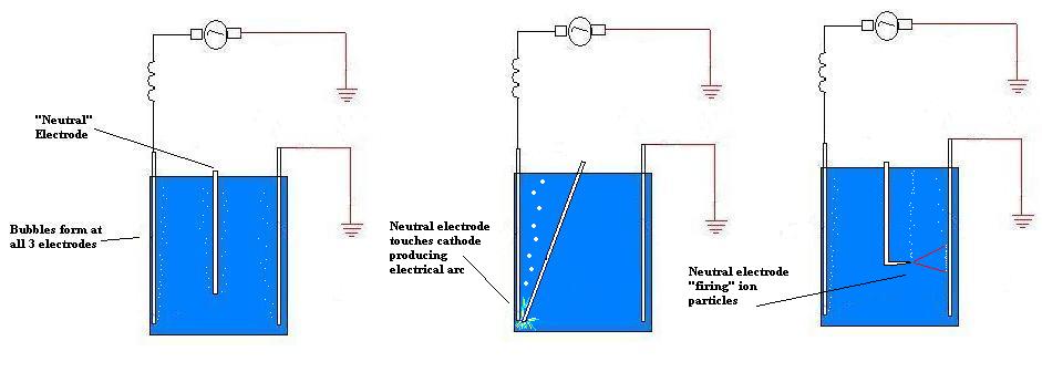
Another modification that I made was to put a third electrode between the two “main” electrodes of a cell. This third electrode was not connected to either of the other two except by being immersed in the solution with them. It was also not separating the cell into two cells by blocking the flow of electrolyte, it was a small, flat piece of stainless and this electrode was positioned exactly between the other two so any ions that were passing would “run into” this neutral electrode. There were three separate effects that I noticed with this setup that I believe are worth mentioning here. The first is that, during the initial “charging” phase there were electrolysis type bubbles forming at this neutral electrode as well as the cathode and anode of the cell. The measured voltage between the two main electrodes was not changed by the addition of the third. There was no measurable potential difference between this electrode and the solution but between the neutral electrode and ground the measured pd was 170 volts. This is interesting because this is the “high end” of normal ac current with 120 volts being the usually measured charge.
The second effect that I noted was that, if the neutral electrode was struck against the cathode or anode, an electrical arc could be created and maintained between the two. Large bubbles of gas were produced at this arc. The really interesting thing about this was that the overall voltage drop and the current through the cell were not affected by creating this arc between either of the main electrodes and the neutral electrode. Also, the arc could be maintained for a minute or more without “welding” the two pieces of metal together (or only slightly tacking them together) even though they were actually touching the whole time. This is probably because the overall current through the cell is so low.
The third effect can be achieved by using either the neutral electrode or the cathode. It is something I like to refer to as an underwater particle beam gun. I observed this effect because the cathode I was using just happened to have a sharp burr on it which I had inadvertently created when cutting the electrode out of a larger sheet of metal. The point of the burr was bent so that it pointed away from the electrode that it was a part of and directly toward the opposite electrode. When power was applied to the cell I noticed that most of the bubbles being produced by the cathode were forming at the point of the burr. Then I saw that, on the anode, the bubbles were forming mostly in a small area, about the size of a pencil eraser, directly opposite the point of the burr on the cathode. It became obvious that the cathode was focusing some type of energy (whether electrical, magnetic or a stream of particles remains to be seen) at the anode and, by so doing, “energizing” that particular part of the anode more than the rest.
The actual usefulness of these effect will not be able to be fully considered until the causes of said effects are known. Until that time I invite anyone who wants to confirm the effects to do so. If the boiler cell above was built it would allow the temperature of the water solution to be increased dramatically as the steam would not have to be released until the desired temperature and pressure were achieved. Another effect that I noticed was that when the steam collects in the upper part of the cell, between the exposed parts of the electrodes above the surface of the solution, the steam spins or rotates between the electrodes from bottom to top, not side to side. I will update this paper as further information becomes available.
-END-
Hydrogen loading of Ni cathode links:
http://www.lenr-canr.org/acrobat/Sankaranarevidencefo.pdf