How it came to be
For some years I have been trying to develop new Stirling designs for Third World Country pumping and cooling . The intention is to find a design that is simple enough to be built by local craftsmen using cheap material, works reliable and has a power-output that is much cheaper than a photovoltaic solution.
In my opinion a liquid-piston design is simple enough and so this is the realm of my researches.
By thinking about liquid-piston designs and the constraint of having a self-starting engine, I had the idea of using a labile equilibrium instead of a balanced or stable one. So I came to the following design . After building and testing the first model it came clear to me, that this design is not good for a reasonable power-output because it has no regenerator, but as an easy-to-build-model it is very, very good. So I will describe in the following lines the simplest (beside West's FLUIDYNE) Stirling engine I know with only one moving part.
Detailed design
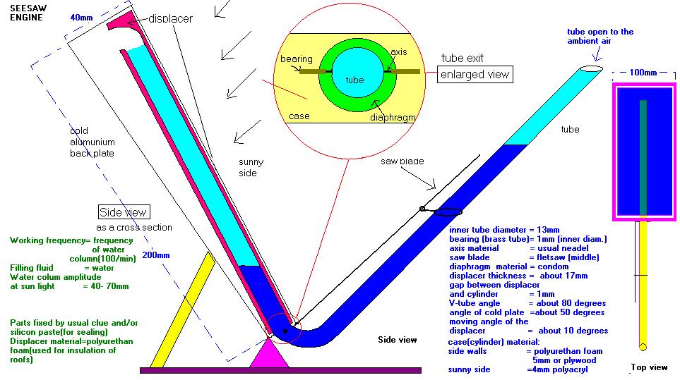
As you can see in the side view in figure 1 the seesaw engine consists of a case similar to a flat-case-collector/cylinder you might know from other solar LTD Stirling engines. The case is 200mm in length and 100mm wide. Its top plate is an acrylic (glas) sheet (4mm thick) and its back plate a 2mm aluminium sheet (best is a cooling plate for semiconductors with fins ). Inside the case is a displacer, made out of polyurethan foam (polysterene will be fine too, for temperatures below 70 degrees Celsius), painted black at its sunny side.
Inside the displacer is a 15mm thick plastic tube (inner diameter about 13.5mm; a plastic tube used for isolation of power wires).
The top plate and the back plate (as you can see from figure 1) are in an angle to each other, that allows the displacer inside to turn around the axis in a small angle. The sides of the case are made of polyurethan foam (like the displacer) and about 8mm thick. Because of the low pressure differences inside, this material can be used, but just as good(or even better) is acrylic sheet or plastic. The engine works without a regenerator and needs a 2mm gap between the displacer and its side walls to let the air easy pass by top -and back plates and the side walls are glued together by acrylic glue (any other glue will do as well as long as it is airtight. In my first test model I even tied it together with thin steel wire like a postal package!).
At the bottom of the case the tube leads to the outside, going in a (about 90 degrees) curve leading upwards and open at the end.
The tube can be made of a single piece of plastic tubing about 400mm long by heating it in the middle and bending smoothly to until the 90 degrees were achieved. Where the tube exits the case, it is sealed by a diaphragm. I used a thin plasic foil and sealed it with silicon paste, but using a part of a condom, will be better in my opinion. Short behind the diaphragm the axis is fixed. Its bearing is made out of a small part of brass tube (inner diameter 1mm!) fixed to the case (glued) with a needle as the axis. After the brass tubes(to the left and to the right of the 15mm tube) were glued to the case (by leaving the needle inside as a fixing during the glue gets hart(dries)), the needle is cut in the middle. You now just need to drill on each side of the 15mm tube a tiny hole, stick the half of the needle inside and glue it with a good glue. If you have cut the displacer already you now need to drill a hole of 15mm diameter in it (as you can see by the figure 1) and stick it on to the tube.
Having assembled all the parts, the displacer and the V-tube should move freely, tipping through the small angle without friction. The blackened surface of the displacer shoud be in full contact with the acrylic glas at the one extreme position and the back plate in full contact with the other side of the displacer, when tipped back. It is good to fix the engine to a ground plate, so that the angle can be adjusted freely (first try a 45 degrees angle;+-20 degrees). Depending on how airtight you have constructed the engine you might need a valve/hole to let out the surplus air when filling the tube with water. The easiest way might be to drill a tiny hole in the side wall and glueing/sealing after filling. Better is to drill a hole for a screw at the lowest point of the case, so you can close it after filling by screwing the screw and in case you water spilled in the case, you can drain it easily.
Now filling the tube half way with water, putting it in an angle so that the displacer almost tips over to the sunny side and heating its acrylic glas side up by the sun (or a 40-100W bulb lamp) would make the engine run already. BUT….this is a very strong labile equilibrium ! So the last important part to assemble is a spring to work against the labile equilibrium which can be adjusted to almost any position. It must be strong enough to even turn the labile equilibrium to a stabile equilibrium if water filled ! To achieve this, I barely glued a saw blade from a fretsaw in parallel position to the extern part of the tube fixed at the case. I built a eight-shaped grip from a paper clip gripping around the 15mm tube and on its other side (in a tiny circle) around the saw blade, so that it can be moved up and down the tube and turned to find the optimal working point. Try it with a middle sized saw blade, fixed in a middle position at about 80mm from the axis for your first test run.
This is just the easiest design to try the seesaw engine, but of course any shape besides the 200*100mm case (for example a disc) will work as well.
How to run it
When finished the assembling and the tube is half way filled with water up to the water columns are at same level, and the position is found where the displacer almost intents to tip over, the first test run can start. Just put the engine into the sunlight. After about 20 seconds try to tip the tube. It should start now ! At least for some strokes. It might happen, that the equilibrium is too labile, balanced or stabile, so you have to try another position of your paper-clip-grip. This is indicated by running for some strokes and stopping at the back plate (heating) position or acrylic plate position (cooling) and staying there. So you have to adjust the spring a little bit closer to the axis and/or in a more middle position. You will have to try for some time but supposed your case is really airtight and the axis friction plus the diaphragm friction is the only friction at your engine, there will be a 'region of positions', where your engine will self-start when heated up.
The funny fact you will find out while seeing your engine running is: IT CANNOT SPEED UP! It always keeps the frequency of the water columns inside and only varies the water columns height (tide). The displacer beats against the acrylic glas and at the back plate and when the temperature difference is small the displacer only tips over a little bit without ever touching the plates.
Try some positions and working modes of your engine - its fun !
If you're a keen builder try to connect an automatic valve inlet at the curve of the tube and an outlet at the extern top of the tube AND YOU WILL HAVE A WATER PUMP. Or just put on your desktop in a sunny place. Anyway build it, have fun with it and send your appreciated comments to me !
I am about to further develop this machine (with a modified extern tube, a regenerator and a light-weight design) to a Third World pumping(or cooling) device (one square meter in size). I applied already for a patent on it and perhaps in the next edition of the Stirling Engine Society's Newsletters you will read about this new design.
In case you are interested in other liquid piston Stirling engines I can supply you with some other design ideas (like rotary liquid piston engines).