piston
The submitted invention is a heat engine or cooling device, basically working
like a Stirling engine.
Usual designs of the Stirling engine (Alpha-, Beta- and Gamma type) as well
as free piston Stirling engines have a sinusoidal 90 degrees phase angle
of their displacer in relation to their piston. By that the optimal differential
temperature in the engine can not be realized.A further problem of the classical
Stirling designs is their complexity, because they have a lot of compounds
(connecting rods, crank etc.)
The submitted invention is a heat engine or cooling device, basically working in a Stirling cycle, built with a free displacer and a movable cylinder and by that with a simplified design and better, discontinuous steering of the displacer.
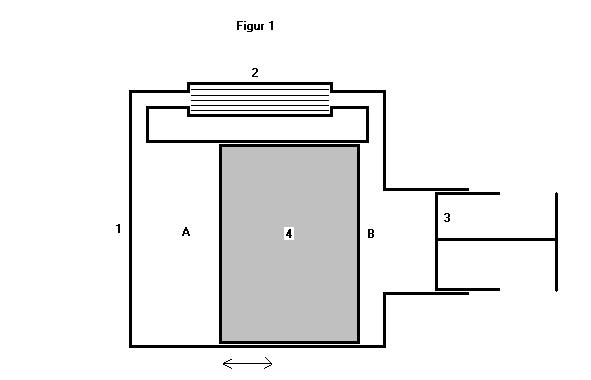
Figure 1 shows the mode of operation at a classical cylinder/piston design.
Although it can be realized using a diaphragm or in a non-axial-movement
design. The power input(cooling device)/output(heat engine) can be built
by using a linear generator/motor, a pumping mechanism or a usual connecting
rod and a crank shaft and a crank (for a rotary movement)(Figure 1 just shows
the schematic design at a non-rotational engine). The major claim of the
invention is on the operation mode characterized by a moving cylinder, a
fixed piston and a free displacer and having these compounds running in the
mode of a Stirling cycle. The mechanical energy is taken off or put into
the engine at the cylinder. Looking at schematically figure 1 the operation
mode as a heat engine can be described like:
The cylinder, filled with the working gas, is supplied with heat at its left
side(cylinder head). The working gas is heated up in chamber A and by that
pressure rises. This pressure is continued through the regenerator(2) and
presses on the piston(3). Since the piston(3) is fix and the cylinder is
movable, the cylinder(1)is moved away and with it the regenerator(2) and
its displacer. In a ideal world the moving-away would last until the pressure
of the hot gas in chamber A would be the same as the ambient pressure. Any
further expansion of chamber A (caused by the kinematic energy of the cylinder)
now causes under-pressure,which slows down the speed of the moving cylinder.
But if then the cylinder is slowed down by under-pressure, the displacer
is not immediately effected by that because it is freely movable (sliding)
inside the cylinder. By starting its travel through the cylinder so, the
displacer displaces the working gas from chamber A to the cold chamber B.
The cooling of the working gas contracts the gas, under-pressure rises and
slows down the speed of the cylinder(1), the relative speed of the displacer
to the cylinder rises and so even more gas gets pushed through the displacer
from chamber A into the cold chamber B. This slowing down/breaking of the
cylinder happens in a expotential mode. If now the displacer(4) has reached
the leftmost point of the cylinder and most of the gas is moved to chamber
B, then the under-pressure is that high, that the cylinder(1) is moved towards
the right side (the side of the piston). This acceleration of the cylinder
in the opposite direction lasts until (again) the ambient pressure is reached.
In a reciprocal way to the above described movement at expansion, the cylinder(1)
is slowed down again by overpressure after moving further back over the ambient
pressure point. The displacer(4), which (reciprocally to the expansion stroke)
keeps its kinetic energy (after being accelerated by the cylinder on its
way back), pushes the working gas through the regenerator(2) back into chamber
A. So if now the cylinder(1) comes to a stand still on his way back to the
piston and most of the working gas is in chamber A as well as the heating
of that gas gave a maximal pressure, again the above described cycle starts
again and by that the engine runs in a cyclic process.

Further application (figure 2) of a spring(5) and a magnet(6) can modify the engine to a self starting engine. The spring(5) has to be dimensioned that way, that it moves back the displacer in a cold stage. The magnet(6) is dimensioned that way, that it holds back the cylinder until the overpressure (by heating of the gas) is that strong, that at the point of letting loose the cylinder is speeded up so much, that it will be bounce against the spring that strong, that the displacer will be moved as much as necessary for a constant cycle. Further it is possible through the use of stops, to constrain the cylinder in its stroke.
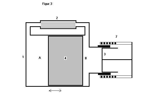 Working as
a cooling machine (according to the Stirling cycle) the invention can be
built like shown schematically in figure 3.In figure 3 a linear actuator(7)
moves the cylinder(1). So at expansion the gas in chamber A is cooled and
by that cools the cylinder walls. If then the actuator(7) doesn't accelerate
the cylinder anymore, the displacer(4) starts moving in relation to the cylinder
and the working gas gets pushed to chamber B via the regenerator. After the
actuator(7) has ended his movement to the right, it moves the cylinder back
to the left. That results in a compression of the gas, which heats the gasup
and by that the cylinder walls get heated.
Working as
a cooling machine (according to the Stirling cycle) the invention can be
built like shown schematically in figure 3.In figure 3 a linear actuator(7)
moves the cylinder(1). So at expansion the gas in chamber A is cooled and
by that cools the cylinder walls. If then the actuator(7) doesn't accelerate
the cylinder anymore, the displacer(4) starts moving in relation to the cylinder
and the working gas gets pushed to chamber B via the regenerator. After the
actuator(7) has ended his movement to the right, it moves the cylinder back
to the left. That results in a compression of the gas, which heats the gasup
and by that the cylinder walls get heated.
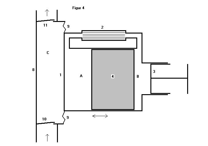
Figure 4 shows the invention combined with a pumping housing(8) (chamber C), a diaphragm(9) and flap valves (10, 11). No matter if the engine is working as a cooling engine or a Stirling engine(when fed with hot water in chamber C), this design directly uses the cylinder(1) as a working piston and by that simplifies the application a lot.
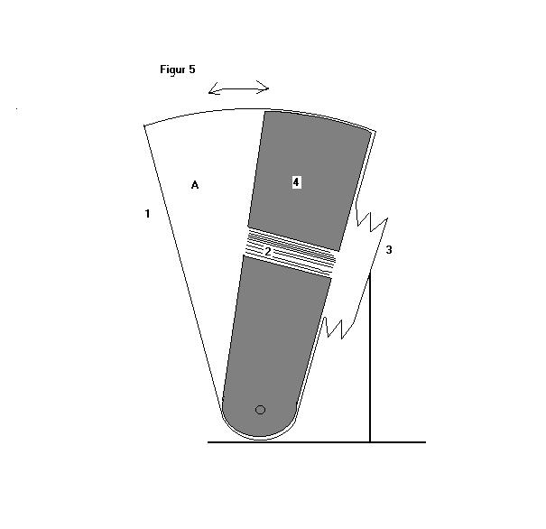
Figure 5 shows the invention in a sectorial(pie slice)design.
A supposed disadvantage of the invention, the bouncing of the displacer against the inner stops or cylinder head can be widely reduced by introducing springs into the cylinder and by choosing a regenerator, that by his (anyway high) turbulence, acts like shocks(in a car) onto the process.
A principle disadvantage of the invention is its vibration. This vibration can be reduced mostly by designing it in a sectorial (pie slice) form and letting it toggle/turn around a pivot in its middle or as a two cylinder application, synchronized and acting in opposite directions.
Further the steady movement of the cylinder makes a direct flame heating problematic, but hot gases or heat radiation (solar) will work well.
The invention supposes, that this invention is a novelty. Researches in published patents showed, that there are only partly similarities to older inventions.
Henry Essex (USA, 1902, patent number US723660) has to be mentioned here.
He invented a Stirling engine with a moving cylinder and a fixed piston.
The difference is, that it moves the displacer by a connecting rod and a
usual crankshaft and by that with a sinusoidal 90 degrees phase angle and
not discontinuously.
Further to mention is E.Franklin (U.K., 1973, patent number in Germany
DE2253296), who as well proposed a free cylinder and a free displacer. But
he moved the piston and by that uses the piston as a working piston. Again
only a sinusoidal movement of the displacer and a more or less 90 degrees
phase angle is reached.
Similar to this patent of Franklin is a later patent of E.Franklin and
E.H.Cooke-Yarborough (U.K., 1973, German patent number DE2259623) and so
is the patent of W.T.Beale (USA, 1969, German patent number DE1933159).
In contrary to these above mentioned patents the invention described and
applied here, has an up to 180 degrees phase angle and a discontinuous steering
of the displacer.
J.Byer (USA 1987, patent number.: US4699093), H.B.P.Roger (Frankreich 1992,
patent number.: FR2677420) and W.Schmied (USA 2000, patent number.:US6032622)
invented combustion engines using movable cylinders and a fixed piston. But
these inventions did not have displacers.
Davey Gordon (U.K., 1990, patent number.: GB2239494), A.J.Rascov (USA, 1990,
patent number.: US4957419) and Th.Witt (1913, DE274278) invented compressors
with valves using stationary pistons and movable cylinders.
So the inventor is convinced, that known problems of other Stirling engine
designs (like high complexity, 90 degrees phase angle, as mentioned at the
start of this description) are removed and by that a high simplicity of the
compounds is reached. This reduces costs. Further this new design allows
- most easy and cheap electric generators,
- miniature applications (Nano-Technology), which would by hardly possible
in classical design,
- most cheap solar LTD applications for Third World countries.
- cooling devices, basically consisting only of a modified loudspeaker, with
a displacer and a can (cylinder) mounted to it.
- better sealed charging of the cylinder.