Presented to the 10th International Stirling Engine Conference
Title: The MC Stirling - a simple and unconventional design
(by Hubert Stierhof)
ABSTRACT
An unconventional basic design is described here, which has its cylinder moving, its displacer free, and its piston stationary. The advantages of that design are simplicity, a rise in efficiency because of its different mode of gas-displacement in relation to classical Stirling engine designs, and that it can be built as a linear engine or as a rotary engine. Talking about the simplicity, the basic design has no connecting rod or mechanical drive for the displacer, even though the displacement can be modelled that way that it fits best in a specific engine design. Negative effects like vibration can be reduced by choosing a near-ball-shape cylinder form and the bouncing of the displacer can be minimised by balancing it. Some simple diagrams are mentioned here to explain the basic mode of movement, which is different to usual sinusoidal movements. Although the problems that arise need further research, the design fits best for refrigeration devices and most simple LTD Stirling engines.
---------------------------------------------------------------------------------------------------
Current Stirling designs (Alpha-, Beta-, Gamma-, and free-piston Stirling engines) all have in common their 90-degrees-phase-angle-behaviour of their displacer. This phase angle leads to a 'misbehaviour' of the displacer and the power piston for almost 180 degrees at each rotation (revolution). After the power stroke, there is expansion, while the displacer is cooling the gas and later on in the cycle there is compression, while the displacer is heating the gas. No doubt, this reduces the thermodynamic efficiency of the engine decisively. Known solutions to that problem are the Yoke drive and the rhombic drive, but both suffer from their complexity of the mechanics necessary for it. So the basic idea here is, to achieve a discontinuous movement of the displacer that keeps it (during the different stages) in a thermodynamic ideal position, while not adding too much vibrations or mechanical components to it.
As a private developer of Stirling engines, I refer to my latest basic design in Stirling engine technology, I call the MC Stirling. MC stands for moving cylinder and in fact, this is the major concept. This approach has some similarities to the TMG of the seventies (E.Franklin and E.H.Cooke-Yarborough). The major difference to the TMG is its stationary piston.
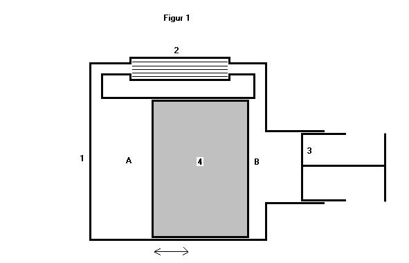
Somewhat deeper explained it's the basic design of an engine, who has its cylinder moving, its displacer free and its piston stationary.
This, quite exotic looking, basic design uses the kinetic effect of inertia to move its displacer i.e. during the power stroke the cylinder is accelerated and through stops inside the cylinder the displacer is accelerated, too. When the cylinder is slowed down (negative acceleration), the displacer keeps its speed and travels over to the other side. The same thing happens vice versa at the cooling stroke.
The basic drawing shows only one of the many possible designs. As well near-ball-shape cylinders, flat cylinders (LTD) and even liquid piston Stirling engines can be built using the moving cylinder approach.
Looking at a rotary engine using this MC design:
The positive that is gained by that is a remarkable simplification of a Stirling engine (basically only two moving parts) AND a rise in efficiency. Besides, it's now possible to have different strokes. We can model a long hot stroke and have a short cooling stroke or vice versa, just the way it's best applicable in the specific engine we build.
The negative that is gained, at first glance, sounds very negative:
1. vibrations (because of higher mass to be moved)
2. bouncing of the displacer against the cylinder head and stops
3. problems with flame heating (moving parts in the flames)
4. no better behaviour of the displacer, than in a classical 90-degrees-phase-angle design, if the displacer stroke equals the power stroke
But things are different, if we have a decent look on these negative features.
Let's start with point (4) in the list , the still bad behaviour of the displacer.
Figure 2

In a classical Stirling engine the displacer is at its highest speed of displacement just when the power piston start its expansion, and the displacement is completed, when the power piston crosses the 90 degrees line.
In a rotary MC Stirling the sinusoidal movement of the cylinder leads to a top speed of the displacer at 90 degrees after full compression (vice versa expansion). That's the point, where half of the expansion volume did its work and that's the point, where the displacer tends to move away from the cold side first. The displacer has its tangential speed and supposed no friction and turbulence of gas (like in a vacuum), and further supposed it would have a expansion stroke of 2 and a displacer stroke of 1, it would reach the other side after another (1/PI/2) about 57 degrees (or 63% of the time) (Figure 3).
Figure 3
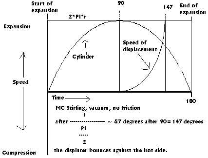
Figure 4 shows a more likely behaviour of the displacement. Herein the displacement start some degrees after the 90 degrees point (because of friction), doesn't reach the highest speed, and slows down rather fast (especially, if friction and turbulence of gas will be that high, that the displacement will even last after the 180 degrees full expansion point, because the cylinder starts moving in the counter direction).
Figure 4

But, as I have already mentioned, we can model the movement of the displacer, although it is freely moving in the cylinder.
So how can we do that ?
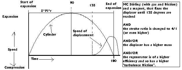
There are different methods to interfere here. First and most efficient, we keep the displacer from starting at 90 degrees, by mounting a permanent magnet to the cylinder (and a small washer to the displacer for example). The magnet will, for example be that strong, that the force of negative acceleration will be strong enough only at 135 degrees to set the displacer free. Doing so we gain a long expansion power stroke. If then we will enlarge the ratio (in our design) of the power stroke to the displacer stroke to 4/1, we can shorten the displacement period (Figure 5).
Figure 5
As well, the mass of the displacer has to be adjusted that way, that the turbulence of gas (caused mainly by the regenerator) is just of that amount, that lets the displacer softly touch the cylinder, with almost no differential speed.
As modelled in figure 5, we can even reach a behaviour that ends after the cylinder has reached its downer most point (180 degrees) and already is travelling upwards. By that, we may even cross the zero-pressure-point (zero-pressure in relation to the crank case pressure) exactly at the downer most point of the cylinder and gain a 180 degrees power stroke for expansion. If then we will model the compression stroke symmetrically, we get a 180 degrees power stroke for compression, too. But, and this might be an important feature of the MC Stirling too, we might as well model the compression stroke different from the expansion stroke for the sake of different temperature gradients, acting here.
So, all of that modelling only fits best at a constant speed and/or delta T working in the engine. Dynamic in speed and delta T still (or especially) is a problem for the MC Stirling so.
Further research has to be done here, for example: Can dynamic adjustment of the magnet be a simple solution ?.
Anyway, let's now assume what we have got:
- we still have the most simple basic design
- we have got rid of the major part of the 180-degrees-misbehaviour of the displacer in a classical Stirling engine
- we've found methods to exactly model the displacement, the way we need it.
- we don't need that much of a flywheel mass than expected anymore (for linear Stirling engines less mass, too), if we model the zero-pressure-point to the end of the expansion.
This is not the ideal behaviour from the thermodynamic point of view, because we still have the 'travel angle' of the displacer, but it's much better than the classical Stirling engine. That means, we gain an enormous rise in efficiency and still have isothermal expansion conditions in the engine.
At linear MC Stirling engines we do not have to have that absolute sinusoidal movement and so the introduction of springs might control the movements even better.
Coming now to point 2 of the list above, the bouncing of the displacer against the cylinder head and the stops. Imagine having a stone in a box, this would really mean shaking and bouncing. In a Stirling engine, this would be different. According of the mass of the displacer, its speed and the turbulence of gas (caused by the regenerator) the displacer will not keep its speed. It will be negatively accelerated by the turbulence, like falling on an airbag of a modern car's security system. Of course there still will be bouncing and so springs have to catch this rest of the force, but a well calculated engine of that kind, running at a constant speed, will have minimised that. The TMG, running for years without maintenance has proven this.
Still we have the vibration problems (1) unsolved. So what can be done here ? My solution might not sound too convincing, but besides 'traditional' methods of having a counterweight at the crank, and/or a near-ball-shape cylinder with a ball-shape displacer (and a short stroke) helps and a two cylinder engine helps, too and, as mentioned earlier, because of our 180-degrees-power-strokes less mass is involved anyway.
In engine designs, which have a flame heating (3) the problem of having a moving part above or through the flames is not very fortunate. So, the slopes of the heat pipes have to move in a left-to-right mode or only (solar) radiation heat is applicable in a Stirling engine of that kind.
When it comes now to designing a Stirling cooler (cryocooler) using the MC technology,
things look different and more positive than described above. The moving of the cylinder turns out to be a further advantage for lower temperature difference cooling. Usual cooling techniques (compression type, absorption coolers and Stirling coolers) do have radiators (fins or fans) to extract the 'heat' from the gas circulating in the cold chamber (room) and there are radiators outside to transport the extracted heat to the ambient air.
A MC Stirling cooler can act differently here. It moves its cold side and his warm side and by that (in combination with a pumping chamber) circulates the air in the cold chamber (room) and to the warm ambient side, too. So we have achieved a design of a cooling device, being its own circulation pump, too. Further more, the MC basic design can be cascaded. To reach low temperatures two or more cylinders can be packed together to one movable part.
Another scope of interest for the MC technology is, no doubt, the LTD sector. Looking at the need of a real low technology solution in Third World countries, the simplest is the best.
The MC Stirling is simplest and needs almost as much parts as a solar heat collector. But even more: The disadvantage of vibrations turns into an advantage of not-needing-any-flywheel.
A flat plate (or bow shape) linear MC Stirling is its own flywheel mass and further more no rotary parts or bearings are needed in an engine of that kind. Even better an engine of that design can be made self starting.
Conclusion and outlook
In short I have described the advantages and disadvantages of the basic design of moving the cylinder, letting the displacer run freely, and having the piston stationary.
Higher efficiency and simplest Stirling engines are the positive outcomes of this MC technology. This is reached by modelling the displacement stroke to its optimum.
The MC Stirling design leads to a significant reduction in production cost, components and sealing problems.
As well it can be supposed, that a higher duration of engines will be achieved.
Further researches have to be made from universities and other institutions to elaborate algorithms to calculate the inner thermodynamics for designs of that kind, and further prototypes of MC Stirling engine have to be built to study this approach. Nevertheless the author is convinced of the advantages in the sector of LTD Stirling engines and Stirling coolers.
Currently a Brazilian project for warm water supply uses the MC technology and a prototype cooling device is built for testing.
by Hubert Stierhof
Bilsteinweg 11
60435 Frankfurt
Germany
Email: hustierhof@aol.com
Internet: http://members.aol.com/hstierhof