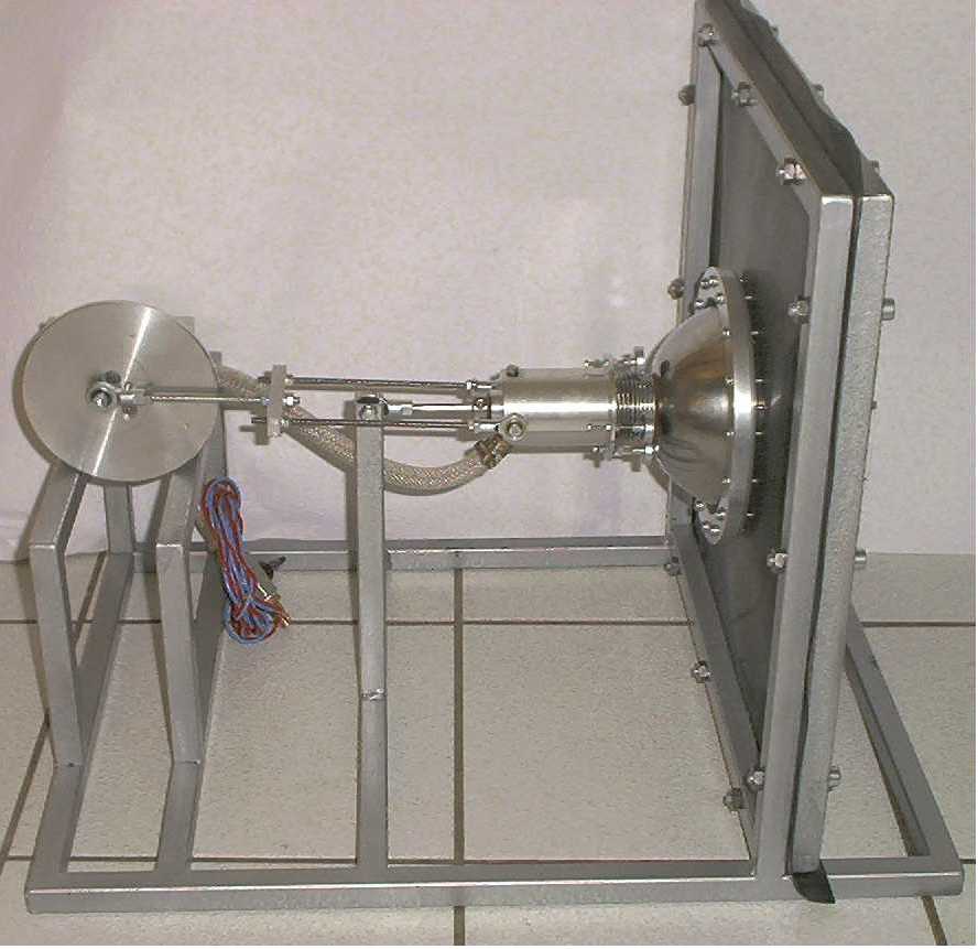
Here is the first prototype using the MC technology for a cooling
Stirling cycle.
Behind the flywheel there is a 40W DC electric engine.
The expansion volume is 15cc, with a 26mm stroke.
In the above configuration:
- the displacer stroke is about 2mm only
- the swept volume (by the displacer) is about 45cc
So the displacer inside is almost about the near-ball-shape
cylinder you see, having its regenerator annular inside.
Behind the piston is an about 80cc buffer chamber, which is
airtight to the rod, leading out to be fixed at the frame.
The buffer chamber was made to be able to charge the engine, while
not getting gas losses through the piston rings.
The big black foil you see (fixed to the metall frame)
is just made of rubber and :
- acts as a curtain between the cold and the warmer cylinder parts
- leads inside the cylinder and is the sealing for the displacer
- acts as a kind of bearing for the cylinder, when moving
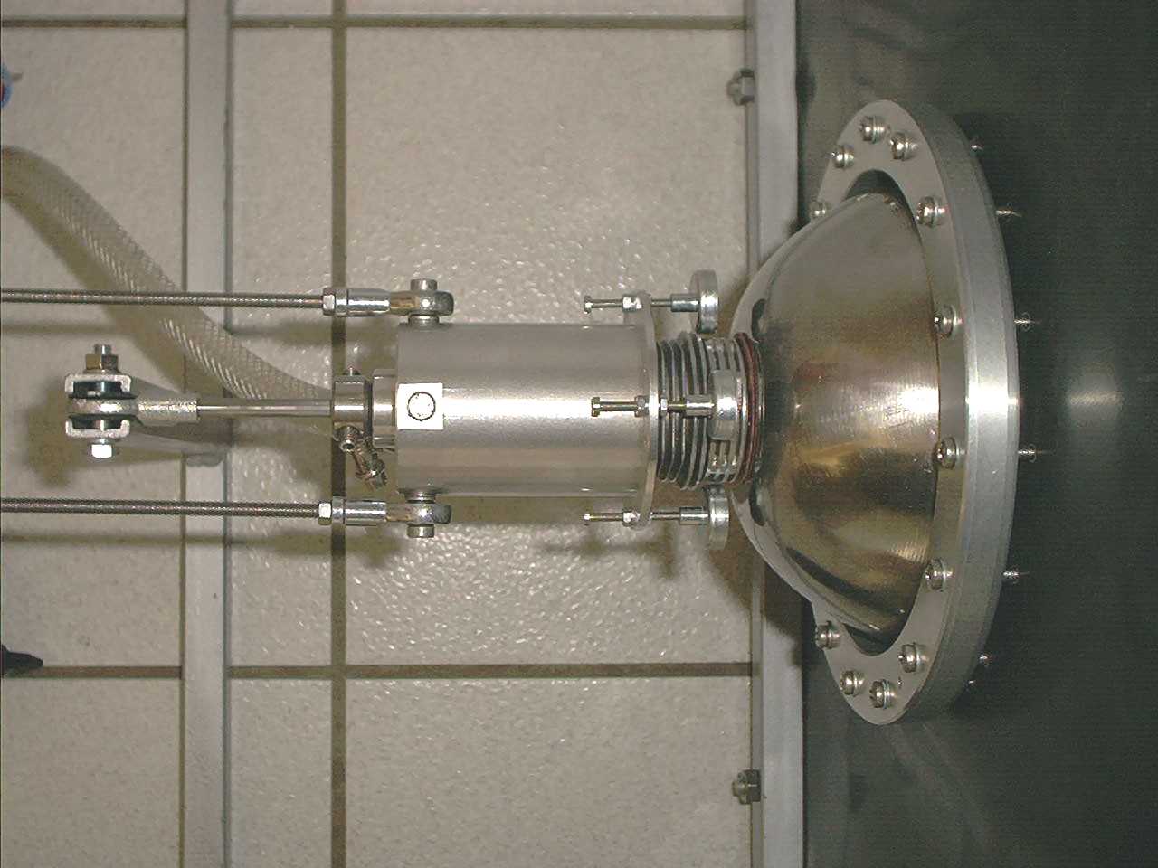
In a detailed view you see the magnets (close to the cylinders cooling fins.
They fix the displacer up to the very last moment to pop of to the
other side while expanding. At the cold end of the engine, you see
a screw, on which usually (for testruns) there are mounted the other four
magnets (for a reziprocal behavior at compression). But they are dismounted
now !
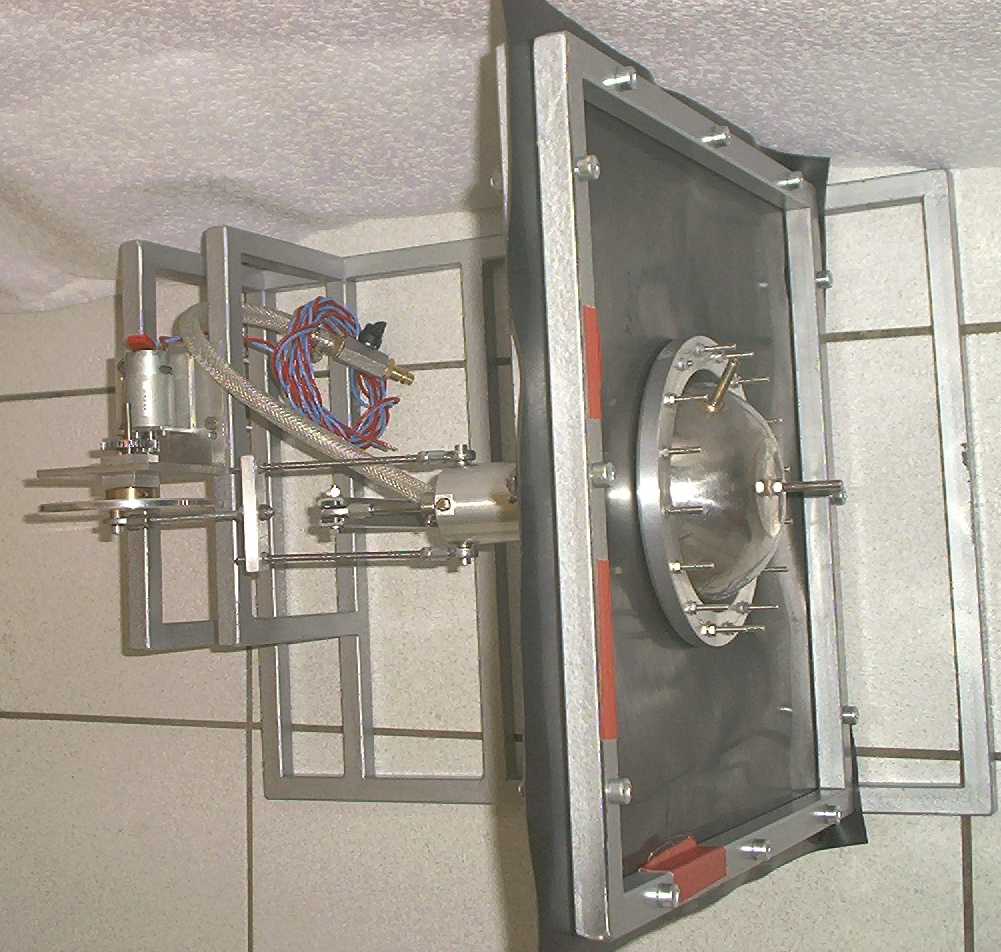
Detailed top view
Seen from the front