
RELOCATING THE ELECTRIC CLUTCH
Here's a shot of the relocated battery. I used 1/2" galvanized electrical conduit and some threaded rod to raise the battery about 4-1/2". It also required that I rotate the air cleaner to put the "snorkel" toward the front to make room for the battery.

This is the electric clutch with the two mounting brackets I made. The brackets bolt to the inside of the frame under the radiator.

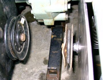
On the left is the tensioner I had to make for the belt that runs from the electric clutch to the mower deck. It is mounted to a 3/16" thick piece of steel with a 1/2" slot. I cut the slot by drilling both ends with a 1/2" bit. Then I used a small blade on a band saw to cut from the bottom edge of the plate up to the first hole. I cut from the front edge of the bottom hole, to the front edge of the top hole. Then rotated the plate and cut back from the rear edge of the top hole to the rear edge of the bottom hole. I then slid the blade back out the first cut from the edge of the plate. I then had the cut from the edge to the hole welded back together. The bottom is a piece of angle with a 5/8" bolt welded to it for mounting the tensioner pulley, and a head bolt from a Mack engine for the vertical spring retainer. The spring is two valve springs from a Mack engine held centered on the head bolt by three thin washers with ears bent to hold the springs in position. On the right is a shot from the other side of the 3/16" plate. Against the plate on the inside, you can see the large 5/8" washer welded to a nut which I used to keep the assembly oriented so the pulley is parallel with the plate. What you cannot see is the spacer between that nut and the pulley which positions the pulley correctly for the belt from the clutch above it. The best part is IT WORKS! After three tries of trial and error fit for the belt, I got it the way I wanted. I finally mowed the lawn with it for the first time with the relocated clutch with no problems.

Here is a shot of the finished product from the left front.

Here is a shot of the finished product from the right front. Now I just need to take everything off again to paint the parts! That may have to wait until fall. In the mean time, I will be working on the sub-frame that connects the loader frame to the rear axle housing. It won't work with the deck under there, so I'll have to make a new one. Then of course, its on to making the mounting hardware for the 54" JD hydraulic lift and angle front blade. It needs to be ready for the coming winter. In the mean time, I may work on putting that little 42" blade on my YM1110D!
Back to Greg's YM1301D!