| |
0. INTRODUCTION
I'm sure somone with some website has
already posted something similar to this page, but
the fact that the information here has been sought
after time and time again indicates that those other
websites are either hard to find or rare.
In this page, I illustrate the five
possible wiring configurations of a dual voice-coil,
DVC, driver unit followed by the corresponding
changes in the Thiele-Small Parameters.
1. DUAL VOICE-COIL WIRING
CONFIGURATIONS
Parallel Voice-Coils
Revc/2
Levc/2
Qms
Qes
Qts = Qms*Qes/(Qms+Qes)
Bl
|

Series Voice-Coiils
2*Revc
2*Levc
Qms
Qes
Qts
2*Bl
|
One Disconnected Voice-Coil
Revc
Levc
Qms
2*Qes
calculate Qts
Bl
|
One Shorted Voice-Coil
Revc
Levc
Qms = (Revc/((Revc*Rmd)+(Bl*Bl)))*sqrt(Mmd/Cmd)
2*Qes
calculate Qts (unchanged, actually)
Bl
|

Adjustment Resistor Connected
to one Voice-Coil
Revc
Levc
Qms = ((Revc+R)/(((Revc+R)*Rmd)+(Bl*Bl)))*sqrt(Mmd/Cmd)
2*Qes
calculate Qts
Bl
|
 One Amplifier per
Voice-Coil
Revc
Levc
Qms
Qes
Qts
Bl
|
Notes:
| Revc |
= |
DC voice-coil
resistance |
|
ohms |
| Levc |
= |
voice-coil inductance |
|
H |
| Qms |
= |
mechanical damping factor |
|
|
| Qes |
= |
electrical damping factor |
|
|
| Qts |
= |
total damping factor |
|
|
| Bl |
= |
electrical-mechanical conversion
factor |
|
Tesla.meters |
| Sd |
= |
effective cone area |
|
square-meters |
| Fs |
= |
resonant frequency of driver |
|
Hz |
| Mmd |
= |
mass of driver's cone |
|
kg |
| Cmd |
= |
compliance of driver's suspension |
|
m/N |
| Rmd |
= |
mechanical resistance in the driver's
suspension |
|
N.s/m |
| Vas |
= |
equivalent volume of the driver |
|
cubic meters |
| |
|
|
|
|
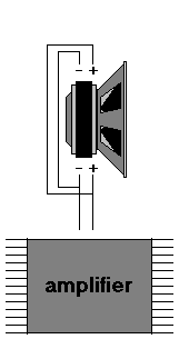
1a. Parallel
Voice-Coils
Using this
wiring configuration, the effective resistance is
half that of one voice-coil's resistance.
Likewise with the voice-coil inductance -- the
effective voice-coil inductance is cut in half.
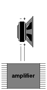
1b. Series
Voice-Coils
This wiring
configuration yields system Revc, Bl and system
Levc that is twice that when using just one voice-coil.
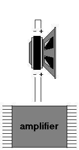
1c. One
Disconnected Voice-Coil
Instead of
having 2 voice-coils to electrical damp the
resonance of the driver, this particular wiring
configuration only uses one voice-coil -- the
other voice-coil is simply not used or "open-circuited."
Because of this, Qes increases by a factor of two.
1d. One Shorted-Voice
Coil
Shorting
one of the voice-coils lowers Qms because the
shorted voice-coil provides electrical damping.
On the other hand, Qes doubles because only one
voice-coil is connected to the amp.
1e. Adjustment
Resistor on one Voice-Coil
The system
Q can be adjusted by putting a suitable resistor
across one of the voice-coils. Qms is a little
lower than 2*Qes when one voice-coil is shorted
while discarding one of the voice-coils does not
change Qms. Values of Qms midway between these
two extremes can be achieved by using a suitable
resistor across one of the voice-coils and it can
be calculated with the above-mentioned equation.
Qes, due to the other voice-coil, is double that
of the value as with the parallel wiring
configuration.
1f. Separate
Amplifier for each Voice-Coil
Treating
each amplifier as ideal voltage sources (having
no output resistance at all), this particular
wiring configuration is essentially the same as
the parallel voice-coil configuration. Thus, the
three system Q values are equal that of the ones
corresponding with the parallel wiring
configuration.
The following
parameters remain unchanged regardless of wiring
configuration,
Fs
Mmd
Cmd
Rmd
Sd
Vas
2. END
I hope the table above will help you in
calculating the corresponding Thiele-Small parameters of
your dual voice-coil driver. Comments, suggestions and
corrections are welcome of course.
3. Corrections Made
- 25 June, 2002: The old highlighted
equations had R when I meant to say total R -- including
Revc. The updated equations above now clearly states this.
I apologize for any inconvenience the old equations might
have caused.
to be continued...
|
|