
 (Click on thumbnails to view full size image.)
Introduction:
The late model Mustang is built on Ford's "FOX" chassis platform derived from the Fairmont in 1978. This chassis uses four control arms to locate the live rear axle; two lower trailing links for for-aft location and two semi-trailing upper links that performed double duties for lateral location as well as controlling the rotation of the axle housing. The assembly was suspended by a coil spring and damper mounted between the lower control arm and the chassis. This four link rear end design was adequate for use in the economy car that it was designed for. But it presents some problems when used in any kind of performance applications when Ford began to add more power to the engine and tried to make the car handle better.
As many Mustang enthusiasts know, the car's handling characteristics can be unpredictable at the least, and downright dangerous at the extremes. The common response is like this: When first going into a turn, the car understeers, and then it can switch rather quickly to severe oversteer while in the middle of the turn. Much has been written about this problem, but here are the basics: The semi-trailing upper links on the rear end pivot in conflicting arcs, so that they can not move very far before they begin to bind. Ford's solution to this was to use soft rubber bushings in the pivots so that they can move somewhat as the suspension needs to. But this also defeats the lateral location purpose of the upper control arms, so the first thing that drivers notice is that the rear of the car feels loose. As the car is turning, and the body rolls, the rubber bushings act like very stiff springs, storing the energy generated by the centrifugal force. At the same time, due to the high roll center, most of the weight in the rear is being transferred to the front tire on the outside of the turn. Eventually, the rear tires have no more traction, and they let go, releasing all that stored energy in the rear suspension, causing the tail to come around.
The other problem with the rear suspension is that it simply does
not help acceleration at all; The axle wraps up from all that soft
rubber bushing, and twists uncontrollably. Ford has used a couple of
band-aid fixes to try to deal with the symptoms including slapper type
bars and axle dampers. Note that the horizontal axle dampers, or
"Quad Shocks", have over 6 inches of travel; they have to deal with a
lot of slop in the rear end.
My Early Fixes:
The first time I tried to upgrade the suspension on my 1987 Mustang GT, I went with the most popular modifications that everyone else was implementing. I got a complete suspension kit from BBK, which included Monroe Formula GP struts and dampers, BBK's specific rate coil springs, and a number of polyurethane bushings. The new springs were stiffer than stock, and lowered the car about 1.5". Similarly, the dampers were also stiffer than stock. I also installed a set of Global West McCastor upper strut mount at the same time. At this time, I'm not certain how much improvement the new parts netted, but the lower riding car bottomed out a lot. I switched to yet stiffer front springs (800 lbs/in from Global West), which eased the bottoming problem somewhat on the front. I would later find out that I was pursuing a course of locking out the suspension with the stiffer springs and dampers; since the stock suspension did not work very well, the first reaction from most after market "tuners" was to prevent it from doing anything at all.
The McCastor kit, on the other hand, proved itself immediately, by using increased caster angles to counteract the kingpin angles inherent in the stock front suspension. This improved cornering, straight line stability, AND tripled tire life. With a little tuning advice from Doug Nordin at Global West, I was able to solve the bottoming problem on the front, but the rear was still not working. On hard corners, the rear end would bottom out, and then would race around to the front. I eventually switched the stock rear springs back in to get rid of the bottoming out. This did not help anything except the bottoming out problem. In addition, the rear end was still loose enough to steer the car under hard acceleration.
The next additions were a set of lower control arms from HPM. They
were prototypes at the time I bought them, but I think they are now
called Megabites. They have urethane
bushings on the chassis end and heim joints on the axle end. At about
the same time, I learned about Global West's new product, called "the
fifth link" or "traction separator" or the
"trac-link", depending on when you saw it.
It was not as radical as the torque arm, and in combination with the
Megabite control arms, it really helped directional stability of the
rear end. They also made the car launch harder, and pretty much
eliminated brake dive. But this setup did little to alleviate the
binding of the upper control arms as they moved; the car still wanted
to whip its rear end around in the middle of a hard turn. A better fix
would have been a torque arm and tracking linkage (Panhard or Watts) of
some sort like what every other serious tracker was using. But
apparently, they had their own problems.
My Latest Fix:
I was intrigued by a couple of new rear suspension designs that, like the torque arm and track link approach, replaced most of the stock components. These designs used newly located upper control arms that were parallel with the lower control arms on each side to control the fore-aft and rotational motions of the axle while allowing non-binding vertical and roll motions of the axle, and used a separate tracking link (Panhard or Watts) to control lateral location. The most interesting of these came from a company called Contex, now called Innovative Performance Solutions, IPS. In addition to the usual set of four parallel trailing links, IPS has a strange set of lateral linkages and bell cranks called the Shaw Link, named after its inventor, Corey Shaw. The Shaw Link served a number of purposes; in addition to controlling lateral location like a Watts link, it could be used to place the roll center in a number of different places, depending on the desired effect. It also works as a weight jacker, which uses roll forces encountered in turns to apply tracking force to the tire on the inside of the turn, where weight transfer would usually unload it. This last function is a little difficult to understand, as according to Corey, it was developed through dynamic analysis of the chassis' reaction to cornering motions and forces. I'm not sure I fully understand it, but I think I'm gaining a lot just from the first two functions; lateral stability and roll center control. This was the set up I got. What follows are descriptions of the installation of the parts, and some driving impressions.
Note: These parts are top rate, so they are not cheap. They are also not exactly bolt-in; some cutting and welding was required.
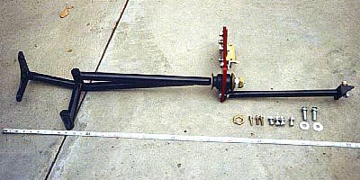
Here is a picture of all the parts that form the IPS Grand Sport rear suspension, mocked up on my driveway. These are the coil-over damper assemblies that I got with the system. While assembling the the coil-over adapter parts, I found that the spring retainers for the rear dampers did not fit properly (see details).
The Installation:
The first step in installing any new suspension components is the removal of the old parts. Procedures on removal of old parts have been covered many times before by other sources, so only the highlights will be covered here. These pictures show the rear end after the old springs, dampers, suspension aids, and the disc brakes were removed. Also removed was the hard brake line that was attached to the axle housing.
Install some kind of bolt or plug in the stock damper upper mounting holes to prevent water leakage. I used the rubber bushings from the old dampers that isolated the rods from the body. Leave the stock upper control arms in place at this time.
The first things to be installed should be the lower control arms. This is pretty straightforward; remove the old arms and put in the new ones. Snug the bolts up, but do not tighten them. The new control arms also come with rubber bushings, and they must be tightened only when the car is on level ground. Now, the first impression of rubber bushings is more rear end wobble, but I later found out that did not happen.
The next things to be installed are the pocket mount brackets for the front pivots of the new upper control arms. They self-align into the upper spring pocket area, and are held in by a number of bolts. Inside the cockpit, underneath the rear seats, the pocket mounts have backing plates that prevent them from tearing through the rather thin floor pan material.
The next items to be installed are the rear brackets for the new upper control arms. This requires welding, and I've never done this kind of welding before, so my work here may not be the best. I will keep an eye on it, and have it professionally welded if I see a problem.
First, loosely install the new upper control arms into the front brackets; snug down the bolts, but do not tighten. Then fit the rear brackets onto the rear eyes of the arms, again snugging the bolts. Then place the brackets on the axle tube, making any lateral adjustments as necessary to center the axle housing. (Measure from the brake backing plates to the frame rails.) Then, slowly jack up the axle housing until the tube is 3.5" from the frame rail. This can be easily done by placing a short length of 2 by 4 between the axle tube and the frame rail. The pinion angle is set by the stock upper control arms and the new lower control arms this way. Clamp the brackets to the axle tube, and weld in place.
Before welding, make sure the standard welding procedures are followed; grind off all rust and clean all surfaces to be welded (this may have to be done before final fitting and clamping of the brackets to the axle tubes), wear thick protective clothing, gloves, and mask, and make sure you have plenty of light to see through the mask.
I started by putting an inch of weld at each end of each edge of the bracket where it touched the axle tube. Then I lowered the axle to get more working room (there really isn't much room at all). Corey warns about using too much heat at one area can cause the axle tube to warp, so weld no more than one inch at a time, and alternate between the two ends of the axle.
Once the brackets have been welded in place, the new upper control arms may be re-attached, and the stock upper control arms may be removed.
The new upper control arm brackets interfered with the anchor brackets for the rear disk brake lines. This car is using the rear disks from the FMS M2300-K brake kit, but I suspect this will be a problem with any rear disk system. Also, the new control arm brackets prevent the use of the stock anti-moan brackets. This is not a big problem, but if it was, the anti-moan brackets can be ground to fit. (I didn't bother, and the rear brakes do indeed moan at times.)
I next installed the cross brace. This required a modification to the fuel filter mounting bracket to make room. There is a frame alignment hole in the frame rail used by Ford during the assembly of the vehicle. This hole aligns with a hole in the trunk floor. IPS provides a threaded backing plate that fits into the hole in the trunk floor. A big bolt is inserted up through the cross member and threads into the backing plate to align the cross member on the frame rail. The cross brace also has holes for installing bolts through the sides of the frame rail. I installed the upper two of these, as they line up with the cross tube of the brace. But drilling the holes for these was a little tricky; the drill will only fit on the outside of the rail, and drilling the hole on that side was easy. Drilling the hole on the inside of the frame rail will take some care. I tried to align the drill bit by eye, and was usually off by about 1/8". A better way to do it would have been to try to first mark the inside holes with the cross brace in place, remove the cross brace, and drill a small pilot hole from the inside to allow the large drill bit to catch it from the outside. It would have been very difficult to drill the full sized hole from the inside. I did not do this, as the cross brace was very difficult to bolt up against the frame rail (I didn't want to do it again), so I laid down some short sections of weld beads to join it with the frame rail.
When I was installing the cross brace, I had to move the fuel lines around. The fuel return line crosses over the pressure line, so that as the cross brace is tightened against the frame, its tube starts to pinch the two lines together. If the lines did not cross, this would not be a problem. In moving the return line, I kinked it a little. I cut off the end, and had to make some kind of coupling to make it connect to the stock fitting again. The stock connector used a fitting with an inner O-ring that the hard line slid into. The hard line had some swaged shoulders on it that worked with the plastic retainer clips to keep it in the fitting. It was not possible for me to make the same swaging, so I had to find something else. The solution I ended up with made use of the stock O-ring fitting. I polished the end of the remaining hard line so that it slid smoothly into the fitting, and I made a couple of aluminum clamp pieces that went around the hard line. They would be held fast to the hard line by a small hose clamp, and would be retained by the stock plastic fitting.
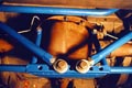
Next to be installed is the axle truss. The truss needs to be bolted to the differential housing and the lower damper mounting bolts. On the housing, 5 of the holes have to be drilled out and tapped for the larger 7/16" bolts provided by IPS. According to a local installer, the holes can be enlarged and tapped, but if the bolts ware ever removed again, they can strip the cast iron threads. Their suggestion was to drill it further out, and install Heli-Coil steel inserts to begin with, so you never have to worry about stripping them out. This is what I did. You will need a 29/64" drill bit for enlarging the holes. The Heli-Coil kit usually comes with only 6 inserts, each of which is about 1/2" deep. The new bolts will require about 3/4" of thread depth, so you will need at least 4 more inserts; two will be used for each hole. There will not be enough material in the differential housing for a 1" deep hole, so drill it for about 3/4" deep, and tap the threads to that depth. The second thread insert will go only about half way into the hole, so the protruding part must be cut off flush with the hole.
Finally, I installed the coil-over springs and dampers, and the Shaw Links. One of the bolts of the Link extended into the cross brace bracket, so I had to grind it down a little. With the Link installed, the bolt barely clears the bracket on the cross brace. But I don't think it will be a problem, as it does not bind or interfere with anything.
The following is a series of shots showing the completed installation. I could not get a true panoramic shot of the whole thing, and I'm really getting to appreciate the troubles the magazine photographers go through when filming in tight places.
(Click on thumbnails to view full size image.)
How well does all of this work? Well the best way to describe it is that it feels completely different from the stock design. In this case, different is good. I no longer experience the jacking effect from hard turns; the rear end stays pretty flat on the ground, instead of constantly swinging back and forth, trying to trade places with the front end. I can launch harder than I used to, although my 120,000 mile engine is probably not the strongest to run that test with. There is no more brake dive that I can detect. I need to rebias my rear brakes now, since they no longer lock up like they used to. In a turn, I can now predictably point the car by application of the throttle. Also, I can power out of a turn much harder than before. The most interesting win is that the ride is actually more supple than it used to be. Bumps are no longer bone jarring like they were with the stiff springs and dampers. This is the result of a suspension that uses its basic design, instead of stiff springs and dampers like most band-aid solutions, to react against roll and cornering forces.
There are a couple of annoying problems with this new suspension, one of which needs to be addressed.
First, the rear springs seem to be too soft, so some parts bottom out occasionally, especially if the preload is set for hard launches. Springs of this type are readily available from the after market, so it is no trick to get another set with greater rates. I just don't know how that would affect handling characteristics. The solution Corey implemented to achieve the ideal geometry is to drill new holes for the front pivot points of the lower control arms. I don't think I want to do this right now.
Second, the Shaw Links make it impossible to use the stock type tail pipes. IPS has custom pipes for this suspension, but I hear that they are not quite a perfect fit either, as they still have interference problems. Plus the rather sharp bends that the pipes need to get past all the parts may introduce more back pressure. This is based on what I've seen and heard, because as of yet, I still have not received the tail pipes that IPS owes me IPS is also working on some side exit pipes as well, but I haven't seen or heard much about them. The cheapest solution right now may be some home made turn-down tips.
Finally, there is now a lot less isolation in the rear suspension components, so every creak and groan that all those parts back there make as they ride over road irregularities are very obvious. This may seem surprising at first, since a plusher ride is usually associated with more isolation. But this annoyance is very minor, and a small price to pay for the much improved ride and handling.
Overall, I am very happy with the performance of this rear suspension. I can now learn to drive the car with confidence, instead of in fear. I plan to take it to some tracks later this year for some real driving tests, and will report the results. Later, I will install the IPS Grand Sport front suspension, and run the tests again for comparison.
Update after about a year: (August 23, 2000)
IPS has replaced the 2.25" ID 300 lbs/in springs with some 2.5" ID 350 lbs/in springs, and now the rear end no longer bottoms out. According to Corey, this may be too stiff for optimal performance, but at least I am reasonably secure from damaging components.
When I installed the bigger springs, I had to use a bigger spacer to set the Shaw links back about 1/4" for clearance. These were included in the original kit. I then had to install some similar spacers on the axle truss as well. This changed the angle on the long bell crank of the link so that it no longer rubbed against the tire well, so a lot of the noise I used to hear from suspension motion is now gone.
A brief driving impression:
I had gotten so used to the squirly nature of the stock Mustang's rear end that I usually drive very conservatively around turns. After reading some other people's experience with the IPS Grand Sport rearend, I was encouraged to try something different. Basically, when going through a turn, if I stepped on the gas to apply power to accelerate out of the turn, the rear end would usually break loose and try to swap ends with the front. With the Grand Sport suspension, I felt the rear end actually dig in, and push the car out of the turn. I tried a couple more times around the same corner, each time applying more power. The feeling was quite exhilerating. I'm still not bold enough to floor the gas pedal around these turns yet, but the suspension is certainly more capable than I am right now around turns.