The following was written by Mike Kendall of AFV INTERIORS WEB MAGAZINE for Vol 1, No. 7, 1999. AFV INTERIORS is a Kit Hobbiest orgranization and he has very graciously given permission to the "AMTRAC PLATOON" to display it on this website, all items in this article are to be used by permission only. Webmaster
Load time is slow due to all the great detailed graphics and pictures.
US Landing Vehicle
Tracked,Personnel, Model 5,
"LVTP-5", Part 1
 Picture
1:
Picture
1:
Plans for the series of vehicles called Landing Vehicle, Tracked (LVT)
date back to at least 1940, perhaps earlier. The U.S. Navy and Marine Corps
approved most of the ambitious Borg Warner Corporation LVT design in the
late 1940's and manufacturing began in the early 1950's. The LVT vehicles
entered service with the US Marines in 1955-56 and replaced a number of
Amtrac types that had been used extensively from WWII into Korea. These
new Amtracs were roomier than their predecessors and were completely enclosed
in light armor. The LVTP (P for "Personnel") was fully amphibious without
preparation, other than closing all lower ports and hatches. Early models
of the LVTP included both an unarmed cargo version as well as a personnel
transport with a MG cupola for ground support located at the front of the
roof. The typical crew load included a Driver in the bow on the port (left)
side, a Commander (Crew Chief) at the starboard bow, and a third member,
sometimes called the Assistant Driver and sometimes the Gunner depending
on the manual you read and the mission of the Amtrac. The vehicle could
hold between 25 and 34 fully equipped Marines, seated in four rows of folding
bench seats--one bench along both sides of the cargo compartment and two
back to back down the center. On the other hand, as many as 45 passengers
could be transported standing up with the middle seats removed and the
side benches folded up against the wall cabinets. The last batch of -5s
were upgraded with a few minor changes to the final version of the Amtrac,
the LVTP-5A1.
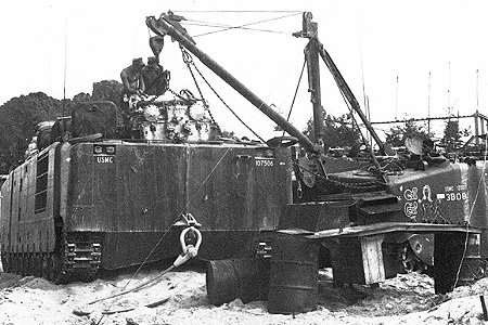
The -5A1 in this USMC photo is having its engine and transmission pulled
by a recovery vehicle version of the LVTP-5, called LVTR1A1. Since we are
looking at the rear of the left LVTP-5A1, we are also looking at the rear
of the powerpack, the white transmission. Notice the engine roof access
panel has been removed and is setting on the barrels to the right, complete
with the later style exhaust/intake modified structure bolted to the center
of the panel.
 Picture
2:
Picture
2:
Amtrac crews in Vietnam operated with the seats removed most of the
time except when the LVTP-5s provided ship to shore duty over extended
distances. When operating in the cargo role, the LVTP-5 could haul 12,000lbs
through the water and 18,000lbs on land, loading and unloading through
the cable lowered ramp at the bow when on land or through large hinged
doors on the roof when at sea. The engine powering all the different variants
of the LVTP was a Continental V-12, liquid-cooled, gasoline motor, which
remained constant throughout the years with only few refinements in exhaust
and air intake ducting in a modified roof vent system in the latest versions.
By 1957 the last LVTP-5 rolled off the assembly line, to be replaced shortly
by an even more refined water taxi.
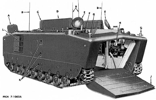
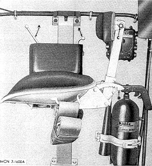
This image and others from the LVTP-5 Marine Corps Maintenance Manual
(ORD-MM-7000A, October, 1957) were provided to us by Museums Branch, History
and Museums Division, Headquarters Marine Corps. The picture illustrates
the layout of the front and right sides of an early LVTP-5. Hydraulic motors
and winch cables lower the large ramp, and with the ramp in the lowered
position you can see the driver's position up on the left sponson near
the bow. Thomas Williams, who crewed an Amtrac in Vietnam, reports they
sometimes connected a cable to the end of the ramp and the top of the opening
so when the ramp was lowered it stopped when it was level (instead of lying
down at an angle). It could then be used as a table for cleaning equipment
or sorting supplies. The hose rising at an angle (below and next to the
driver's seat) is one of the bilge discharge hoses. The driver's domed
over-head hatch is seen in the open position.
On this near side of the Amtrac sat the vehicle commander, usually a
Crew Chief, and he had the same over-head cupola and hatch as the driver.
The interior paint color of these hatches was the same as the primary exterior
color, USMC green, but most of the surface was covered with a thick, black,
leather head bump pad. The large cargo doors on the roof are shown in the
open position, the hatches hinged on their outside edges and folding in
the middle to fully expose the interior of the compartment below. The inside
color of these long hatches was also generally the exterior color, USMC
green. Down inside, the long passenger seats were padded and covered with
flat black leatherette on the surfaces and all had USMC green painted support
legs. Also visible here is one of the rear engine access hatches, opened,
as well as the radiator air exhaust port on the side of the hull.
This is the first of a two part series on the LVTP-5. This part will
cover the general development of the vehicle and the commander's station
on the right side while Part 2 will explore the driver's area and the engine/transmission
compartment at the rear.
 Picture
3:
Picture
3:
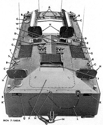
From the same maintenance manual we have this top and rear view of
the basic LVTP-5. The engine is located in its own compartment at the rear
of the hull and a large engine access panel on the roof can be unbolted
to allow access to the engine and removal of its major components. From
inside the vehicle there is also access to the engine through a large panel
on the back fire wall of the cargo compartment. On top of the roof engine
access panel you can see the early exhaust grating and deflector that will
be changed later with the LVTP-5A1 version of the Amtrac. To either side
of this panel are two engine access hatches used by the crew for engine
access for minor maintenance. There are two domed air blower covers on
the roof, the one closest to us at the left is for the scavenger blower
in the engine compartment and a similar blower is located on the forward
left corner of the hull, behind the driver's hatch. These blowers exhausted
stale air from inside the LVTP and fresh air then entered from open hatches
or three smaller ports also located on the roof. Even with this system,
the air inside a closed up and operational LVTP-5 was normally pretty thick.
Forward of the two engine access hatches are two radiator intake grills
covering the location of the twin engine radiators and fans below. While
on land, the engine driven fans drew cooling air into the ducts and through
the radiators inside, then exhausted the air through the hull side grates.
When in the water, the driver turned off the fans and the sealed radiator
compartments were allowed to partially flood to cool the radiators. That
is why you often see water pouring from the side grates when Amtracs come
ashore. Forward of these grills are two entrance hatches into the cargo
compartment with radio antenna bases outboard and two of the inboard fresh
air ports I mentioned earlier. Taking up most of the roof (forward of the
two hatches) are the large opened cargo hatches, in this case showing how
they are articulated in the middle to fold back on themselves. Ladders
were stowed to the outside surface of the cargo hatches and were used at
the back edge when the hatches were open to get from the cargo compartment
floor to the roof and then outside. The driver's cupola and surrounding
vision blocks are at the front left of the roof and the commander's are
to the right. In this case, the MG turret is not mounted and a round cover
plate is bolted on the roof in its place.
 Picture
4:
Picture
4:
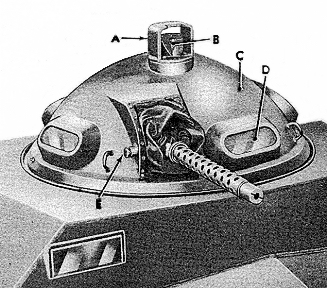
This is the commander's closed over-head cupola and hatch with its
four surrounding M17 periscopes that allowed clear views forward and to
the side. Another periscope, an M17C, is aimed across the raised roof section
for a diagonal view of the opposite front corner of the Amtrac. The hatch
is opened with the assistance of a set of torsion springs inside the hollow
hinge bar you see here. A spring-loaded hook holds the cover latched in
the open position and the hook can be released from inside the hull by
pulling down on a hook shaped eye located at the base of the cupola. A
locking handle on the under side of the hatch locks it closed and provides
a grip for opening and closing the hatch. A watertight seal keeps sprayed
water out and there are rubber seals around all the periscopes for the
same reason. Just outside the cupola you can see a number of items on the
roof including another of the fresh air intake ports next to the antenna
base (at the lower right of the picture). Also seen here is one of the
large lifting eyes--another is located next to the driver's cupola on the
right and two more on the aft roof. Forward of the hatch you can see the
armored cover for the blackout bow marker light and the unprotected light
next to it is a detachable driving light. At the far right end of the hatch
hinge you can see the hold open hook that we mentioned earlier welded on
the domed cover.
 Picture
5:
Picture
5:
If we open the commander's hatch and lower ourselves down, we will
stand first on his seat, and then step down from the sponson onto the floor.
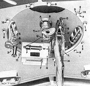
The commander's seat and surrounding gear would look like this image from
the Manual. We are looking across at the seat, which is mounted on a support
post that is bolted on top of the sponson and also onto the hull wall.
The seat is composed of a metal formed bottom seat pan (normally black,
but shown here white) that slides up and down the support post in a similar
way to driver's seats mounted in many US tanks. This allows the occupant
to ride either under armor or with his head out of the hatch. The spring
for raising the seat when the height adjustment lever is pulled and your
weight is lifted off is hidden inside the post. The seat adjustment levers
can just be seen behind and above the padded lever control box next to
the seat. The control handles stick up above the padding and includes the
forward lever for vertical seat adjustments, and the rear handle for horizontal
adjustment (B). The wide OD green seat belt is shown rolled up on either
side of the seat bottom. The height of the seat back is adjustable via
a wing nut (C) and the back can be reclined by the control lever at the
base (D). Directly behind the seat is the one portable CO2 fire extinguisher
carried in the vehicle although there are three others fixed in the engine
compartment for fires back there. The commander's green radio control box
is mounted at his right shoulder and is where he plugs in his headset and
microphone for communication in and out side the vehicle. The padding on
the seats is typically covered by flat black or gray colored plastic imitation
leather, but USMC green canvas covered seats are also seen and are probably
a repair of the original.
 Picture
6:
Picture
6:
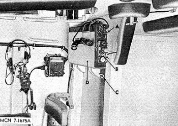
A clamp on the bulkhead directly behind the commander could hold a
small AN/PRC radio, shown in its up and stowed position in this handbook
illustration. The radio could be either an 8, 9, or 10 unit, depending
on the mission of the Amtrac, and it is connected to the forward starboard
antenna by the black cable you see to the upper right. The set is powered
by an internal battery and may be operated inside the vehicle, from a semi-permanent
ground installation outside, or while being carried by the operator. The
AN/PRC is matched with a handset H-33/PT that plugs into the AUDIO jack
on the panel. Because there is a high noise level in the vehicle, a headset
microphone H-63/U and chest set group are proved for the commander as you
see here; the driver has a similar radio set up. The commander's seat back
is directly below and his over-head cupola is above. The vision blocks
were easily replaced by unlatching the side handles on the mounts and then
lowering the glass block into the vehicle. A replacement could then be
inserted and the holders latched secure again. At the upper right corner
of the picture is the control handle for the fresh air intake port at this
position. Armor on the LVTP-5 was thin and ranged from 1/4 to 5/8in thick.
It was butt-welded and reinforced with structural members inside providing
a very robust, if uninspired, hull configuration.
 Picture
7:
Picture
7:
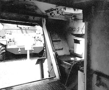
Here is the commander's position and opened ramp from inside a preserved
LVTP-5A in an outside display. This and other photos in this series of
articles were taken by Kelly Jo Williams and loaned to INTERIORS by Thomas
Williams. Although a bulkhead hides most of the commander's seat in this picture, you can still see the front edge of the contoured base pan with the seat in the elevated position. Attached to the wall to the right of the seat is a storage
box for viewing blocks and forward of the position is a bracket for a first
aid kit and box type flashlight. To the left is the cable and pulley for
raising the ramp along the edge of the opening and just to the right is
what's left of a bracket on the front wall for four cans of .30cal ammo.
Notice the anti-slip covering on the floor plates and the dark color of
the floor here as well as on top of the sponson.
Most of the electrical cables on the ceiling forward of the commander's
hatch are attached to the infrared blackout lights and headlights we saw
earlier on the exterior of the vehicle. Behind the seat is a wall full
of storage boxes and cabinets for tools and other gear; the wall cabinets
extend clear back to the right side exit hatch. The interior walls and
ceiling of the vehicle are painted white, originally gloss finish but fading
with wear and time to dull white. The floor was usually painted flat black
or USMC forest green, but you will find it repainted white in photos taken
during Vietnam. Most of the webbing belts inside, such as the seat belts,
are OD green.
 Picture
8:
Picture
8:
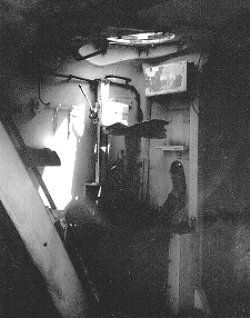
Another image from the same vehicle, although a bit darker than the
previous, shows the same position but from the opened ramp. The seat is
clearly seen here, although the back is missing. Notice the bracket holder
for the AN/PRC radio on the bulkhead behind the seat. The bracket hooks
on the hull wall forward of the seat controls were to hold the vehicle
log book and was also handy for hanging the commander's headset and microphone.
A bracket for a first aid kit and another for a box shaped flashlight are
further forward and can't be seen here. The diagonal white support on the
left is the right ramp opening support brace, and the cable running up
its top side is the ramp control cable. The hose running up the sponson
next to the seat and ending at the roof is the right bow bilge pipe, leading
up from the pumps under the floor to a discharge exit on the hull roof.
 Picture
9:
Picture
9:
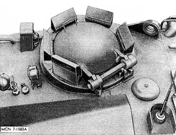
A small one-man MG turret was often mounted in the roof between the
commander and driver's hatches in those vehicles designated as personnel
carriers. The turret mounted the familiar .30cal 1919A1 Browning machine
gun in a cradle that was manually elevated and depressed on two trunion
pins with an elevation handle. Elevation was from +60 to -15 degrees and
on top of the domed turret is the gunner's periscopic sight assembly. The
gunner could use any of five vision blocks around the turret cupola, combining
to provide a complete 360 degree view around the vehicle roof. There were
two additional vision blocks on the front surface of the elevated turret
base attached to the roof and one of these blocks can also be seen in this
illustration. Inside the vehicle, there were locations for reportedly stowing
2,000 rounds of .30cal ammo stored in cans (250/can), but in action in
Vietnam additional ammo was stowed inside, stashed anyplace an ammo can
would fit. Below the turret could be set a short platform for the gunner
to stand on in order to better use the vision blocks and reach the gun
equipment. It was not necessary for gunners over 6ft tall.
 Picture
10:
Picture
10:
This image of the inside of the turret illustrates many of the control
details. The MG gun mount at the right is complete with a green canvas
spent shell bag hanging down from the exit chute of the receiver. The MG
firing trigger is visible here (G) as well as the elevation handle (L),
although the gun could be elevated by use of the MG handle alone. To the
far left is the hand crank for rotating the turret, which is attached to
a geared drive mechanism surrounding the turret. The .30cal ammo box support,
which would hold a typical 250 round .30cal ammo can, is directly in front
of us and a green painted cylindrical battery box (M33 Instrument Light)
for the light bulb inside the periscopic sight is attached to the box support.
The M111B periscopic sight has a large rubber eye/face pad and the sight
tube is articulated in elevation to follow the gun. Above, on the ceiling
of the turret dome and off set to the rear, is a small circular head pad
glued to the armor where the gunner's head would most likely bump when
he used the gun. Only a part of the pad is seen at the top of the image.
Notice the two viewing blocks in the turret support structure, seen here
at the bottom of the image.
 Picture
11:
Picture
11:
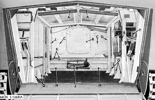
The LVTP designers located the ramp at the bow in order to make amphibious
assaults more practical than earlier Amtracs. The bow ramp placement also
allowed for a more balanced load/engine ratio when landing, since the power
pack was at the rear. Looking directly back into the hull you can get a
feel for the expansive area available for carrying cargo or troops when
the seats were removed. The lower deck flooring was steel, covered with
non-slip skid plate, and was 15ft long from the base of the ramp to the
engine bulkhead and over 7ft wide. Five companies built LVTPs, including
Ingersoll, St. Louis Car Company, Food Machinery Company (FMC), Baldwin-Lima-Hamilton,
and Pacific Car and Foundry. Around 1,000 were completed and handed over
to the Marines.
Under the floor is the bilge space and a number of individual fuel containers
to store the total of 456gal of 80 octane gasoline for the thirsty Continental
engine. The vehicle's travel range was around 250 miles on land and 65
in calm water. At the back of the compartment you can see the central engine
access hatch flanked by cargo pad tie down eyes. Down on the bottom of
the back firewall are access panels for the four vehicle batteries (H),
two secured in each cabinet. Between the battery compartments is a typical
USMC bracket box containing a set of pioneer tools. Over-head you can see
the closed cargo hatches and the handles for releasing the hatches are
visible at this end of the opening (A). At the right side of the photo
is the driver's area and directly behind him are open racks to stow equipment,
including a number of possible radio sets. The long bench seats along the
sides and center of the compartment have been removed completely from this
LVTP-5. Normally, the side benches would be folded up along the walls where
you see the vertical roof supports. When folded, the unique zigzag pattern
of the bottom seat cushion supports would be visible on both sides of the
space. The roof support beams add strength to the structure and there are
additional beams welded around the vehicle hatches and especially the cargo
doors on the roof. As I mentioned in Part 1, the primary interior color
in the LVTP is generally gloss white, with a flat black or USMC forest
green floor. But, repainted white floors are as common in period photos
as the darker original factory paint.
Continue on the Page Two
